Electric control box protection device of numerical control machine tool

A protection device, the technology of CNC machine tools, applied in maintenance and safety accessories, metal processing machinery parts, metal processing equipment and other directions, can solve problems such as short circuit of instruments, damage to tight components of instruments, etc., to achieve good dust and dust removal, complete functions, simple structure

Inactive Publication Date: 2017-12-08
CHENGDU RONGCHUANG ZHIGU SCI & TECH
View PDF0 Cites 7 Cited by
  • Summary
  • Abstract
  • Description
  • Claims
  • Application Information

AI Technical Summary

Problems solved by technology

[0002] Numerical control machine tool is the abbreviation of numerical control machine tool. It is an automatic machine tool equipped with a program control system. Processing parts, so CNC machine tools generally use electric control boxes. At present, electric control boxes on the market have a lot of internal electronic instruments, so they will generate a lot of heat, which will be dissipated through the cooling holes on the wall of the electric control box However, because the heat dissipation holes are in direct contact with the outside world, it is easy to cause the metal floating dust generated when the lathe is working to float into the electric control box, and the static electricity on the metal floating dust will cause short circuits in the instruments in the electric control box and damage the instruments in the instrument. Compact components, for this reason we propose a CNC machine tool electric control box protection device to solve this problem

Method used


Image

  • Electric control box protection device of numerical control machine tool
  • Electric control box protection device of numerical control machine tool

Examples


Embodiment Construction

[0014] The following will clearly and completely describe the technical solutions in the embodiments of the present invention with reference to the accompanying drawings in the embodiments of the present invention. Obviously, the described embodiments are only some, not all, embodiments of the present invention.

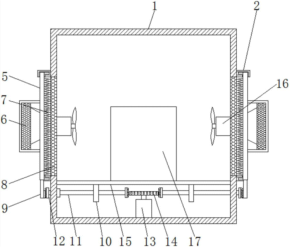
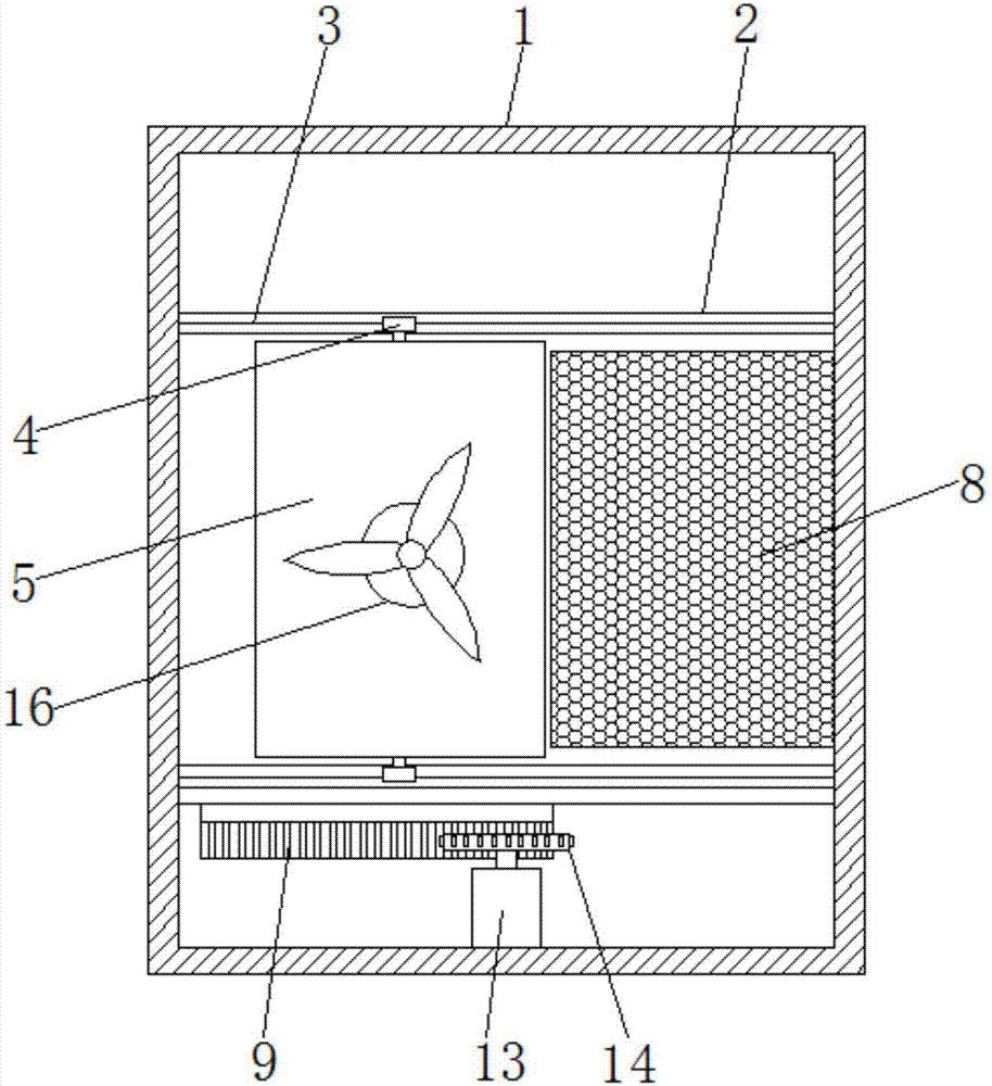
[0015] refer to Figure 1-2 , a protective device for an electric control box of a numerical control machine tool, comprising a box body 1, the outer wall of the box body 1 is symmetrically welded with slide rails 2, the inside of two sets of slide rails 2 are provided with chute 3 along its length direction, and the two sets of chute Sliders 4 are slidably installed inside the 3, a baffle 5 is installed at one end of two groups of sliders 4 protruding from the chute 3, an air intake cover 6 is installed on the side where the two groups of baffles 5 are far away from each other, and two groups of baffles 5 Brushes 7 are installed on the side close to each other, and ...


PUM


Abstract

The invention discloses a protection device for an electric control box of a numerically controlled machine tool, which comprises a box body, slide rails are symmetrically welded on the outer wall of the box body, slide rails are provided inside two sets of slide rails along their length directions, and inside the two sets of slide rails are A slider is installed slidingly, a baffle is installed at one end of the two sets of sliders protruding from the chute, an air inlet cover is installed on the side where the two sets of baffles are far away from each other, and a brush is installed on the side where the two sets of baffles are close to each other. The side of the two groups of brushes close to each other is equipped with the first through hole opened on the shell wall of the box body, the two groups of first through holes are inlaid with filter screens, and the bottom of the two groups of baffles is welded along its length direction. For the rack, a partition is installed inside the box, and the partition and the inner wall of the box form a first cavity and a second cavity. The invention has simple structure and complete functions, can play a good role in dust prevention and dust removal for the electric control box, and also has the effect of heat dissipation and cooling, is beneficial to the operation of the electric control box, and is suitable for market promotion.

Description

technical field [0001] The invention relates to the technical field of numerical control machine tools, in particular to a protection device for an electric control box of a numerical control machine tool. Background technique [0002] Numerical control machine tool is the abbreviation of numerical control machine tool. It is an automatic machine tool equipped with a program control system. Processing parts, so CNC machine tools generally use electric control boxes. At present, electric control boxes on the market have a lot of internal electronic instruments, so they will generate a lot of heat, which will be dissipated through the cooling holes on the wall of the electric control box However, because the heat dissipation holes are in direct contact with the outside world, it is easy to cause the metal floating dust generated when the lathe is working to float into the electric control box, and the static electricity on the metal floating dust will cause short circuits in t...

Claims


Application Information

Patent Timeline
Patent Type & Authority Applications(China)
IPC IPC(8): B23Q11/12
CPCB23Q11/126
Inventor 张岱齐弘文
Owner CHENGDU RONGCHUANG ZHIGU SCI & TECH
Why Eureka
Try Eureka