
Rubber handle supply mechanism

A technology of feeding mechanism and plastic handle, which is applied to conveyor objects, transportation and packaging, etc., can solve problems such as low efficiency, and achieve the effect of reducing labor costs and improving production efficiency.

Active Publication Date: 2017-12-08
湖南锐科机器人技术有限公司
View PDF5 Cites 6 Cited by
  • Summary
  • Abstract
  • Description
  • Claims
  • Application Information

AI Technical Summary

Problems solved by technology

Many processes in the field of traditional hardware equipment manufacturing are manually installed, such as the installation of the rubber handle of the vise, which uses manual installation, which is inefficient

Method used


Image

  • Rubber handle supply mechanism
  • Rubber handle supply mechanism
  • Rubber handle supply mechanism

Examples


Embodiment Construction

[0029] In order to enable those skilled in the art to better understand the technical solution of the present invention, the present invention will be described in detail below in conjunction with the accompanying drawings. The description in this part is only exemplary and explanatory, and should not have any limiting effect on the protection scope of the present invention. .

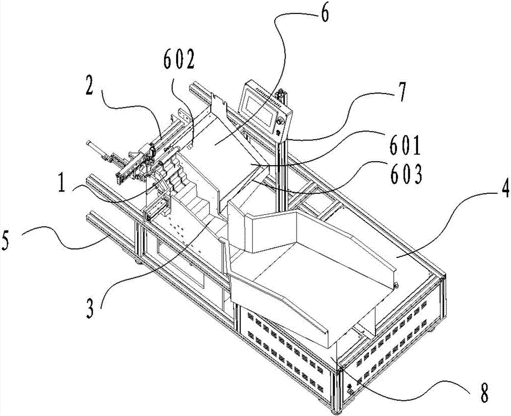
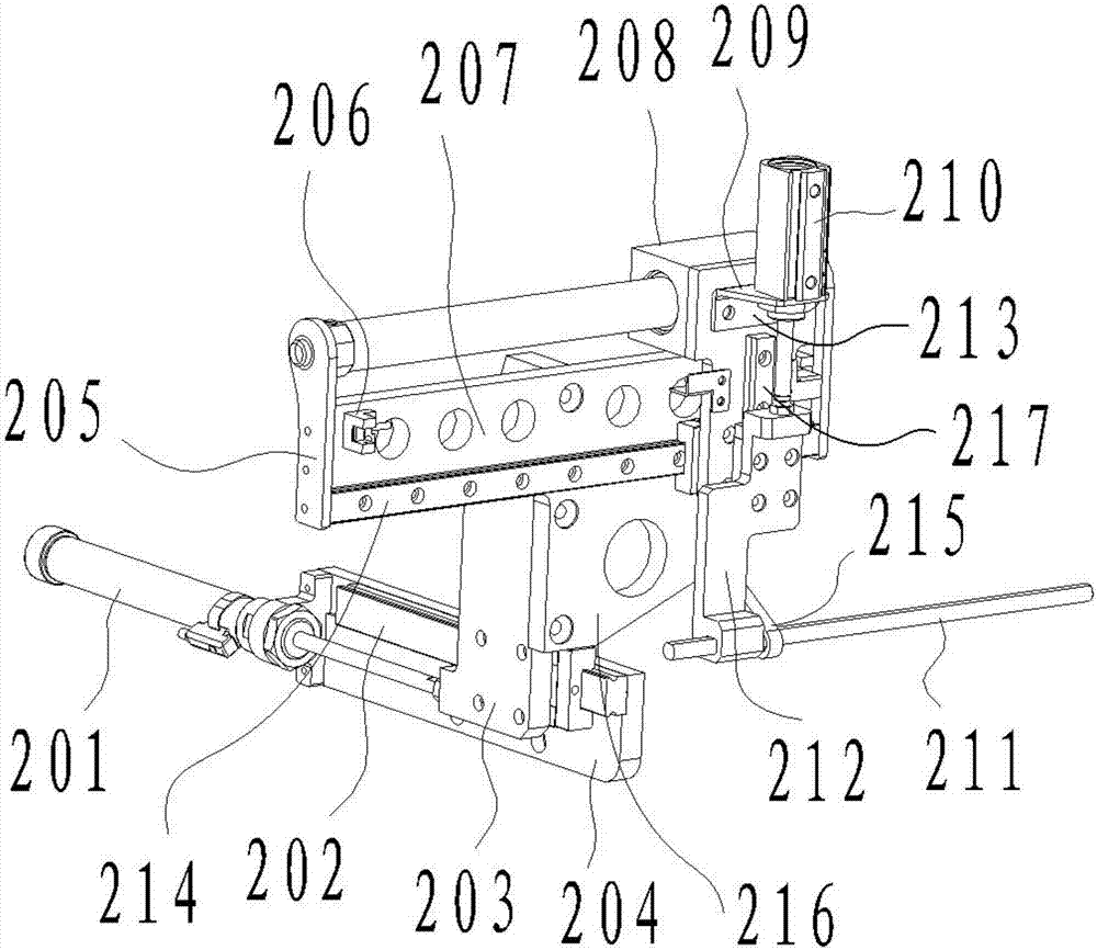
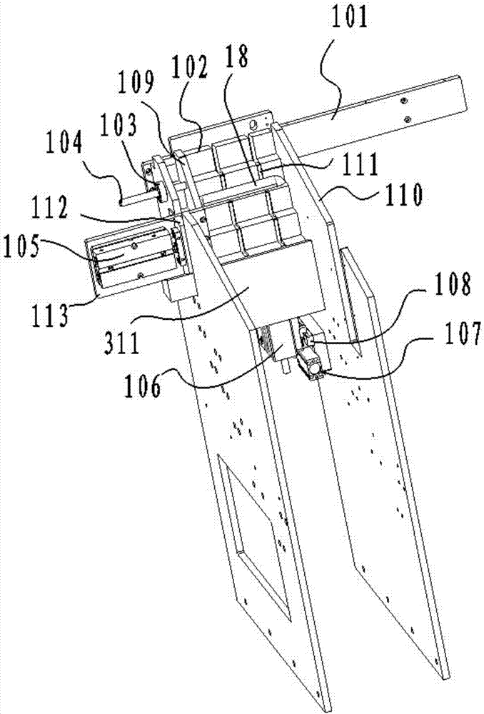
[0030] Such as Figure 1-Figure 10Shown, the concrete structure of the present invention is: a kind of rubber handle feeding mechanism, and it comprises frame 5; Said frame 5 is provided with feeding device 3, electric cabinet 4, intermittent feeding mechanism 1, rubber handle detection conveying Device 2, feeding device 6 and control device 7; one end of the feeding device 3 is connected to the intermittent feeding mechanism 1; the top of the intermittent feeding mechanism 1 is provided with a rubber handle detection and delivery device 2; the rubber handle detection and delivery A feeding device 6 i...


PUM


Abstract

The invention discloses a rubber handle supply mechanism which comprises a framework. A feed device, an electric cabinet, an intermittent supply mechanism, a rubber handle detecting and conveying device, a return device and a control device are arranged on the framework; an end of the feed device is connected with the intermittent supply device; the rubber handle detecting and conveying device is arranged on the top of the intermittent supply device; the return device is arranged on a side of the rubber handle detecting and conveying device; the return device is communicated with the feed device. The rubber handle supply mechanism has the advantages that rubber handles can be intermittently supplied, each end with holes can be automatically identified, then the rubber handles with the ends with the holes can be conveyed to next link, each end without holes can be reversed, then the rubber handles with the ends without the holes can be conveyed again, accordingly, the conveying efficiency can be greatly improved by the rubber handle supply mechanism, and the labor cost can be reduced.

Description

technical field [0001] The invention belongs to the field of automation equipment, in particular to a rubber handle feeding mechanism. Background technique [0002] In order to improve productivity and eliminate backward production capacity, small and medium-sized enterprises are gradually developing in the direction of automation. Many processes in the field of traditional hardware equipment manufacturing are manually installed, such as the installation of the rubber handle of the vise, which is manually installed, which is inefficient. In order to realize the automatic production of the vise, one of the important links is its feeding device, and the feeding device needs to realize the placement and orientation of the rubber handles. The rubber handles are transported to the position detection link one by one intermittently. In the detection process, if the direction of the rubber handle is consistent, continue to the next step, and the inconsistent rubber handle will be t...

Claims


Application Information

Patent Timeline
Patent Type & Authority Applications(China)
IPC IPC(8): B65G47/26B65G47/74B65G47/24
CPCB65G47/24B65G47/26B65G47/74
Inventor 刮国良
Owner 湖南锐科机器人技术有限公司
Learn More