
Closed-loop phase-locked drive circuit for mems gyroscope

A driving circuit and gyroscope technology, which is applied to gyroscope/steering sensing equipment, gyro effect for speed measurement, instruments, etc., can solve the problems of long establishment time of analog closed-loop drive, large noise, unstable frequency and phase, etc., to achieve Avoid Amplifier Oscillation, Low Noise, Effect of Positive Voltage Phase

Active Publication Date: 2020-10-16
中科芯未来微电子科技成都有限公司
View PDF4 Cites 0 Cited by
  • Summary
  • Abstract
  • Description
  • Claims
  • Application Information

AI Technical Summary

Problems solved by technology

[0004] In order to solve the traditional analog closed-loop drive settling time is long, the noise is large, the frequency and phase are not stable enough, etc., the present invention provides an analog closed-loop drive circuit based on phase-locking technology

Method used


Image

  • Closed-loop phase-locked drive circuit for mems gyroscope
  • Closed-loop phase-locked drive circuit for mems gyroscope
  • Closed-loop phase-locked drive circuit for mems gyroscope

Examples


Embodiment Construction

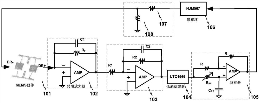
[0031] In order to make the object, technical solution and advantages of the present invention clearer, the present invention will be further described in detail below in conjunction with specific embodiments and with reference to the accompanying drawings. The following description of the embodiments of the present invention with reference to the accompanying drawings is intended to explain the general inventive concept of the present invention, but should not be construed as a limitation of the present invention. figure 1 It is the schematic diagram of the circuit system of the specific embodiment of the present invention. exist figure 1 Among them, based on the principle of electrostatic drive and capacitance detection, the detection terminal of MEMS gyro sensitive device 101 outputs a weak current signal, which is converted into a voltage signal through a transimpedance amplifier 102, followed by an inverting amplifier 103, so that the output voltage signal is in phase wit...


PUM


Abstract

The invention provides a closed-loop phase-locked drive circuit for a MEMS gyroscope. The closed-loop phase-locked drive circuit comprises a MEMS gyro-sensitive device (101), a trans-impedance amplifier (102), an inverting amplifier (103), a low-pass filter (104) and a resistance voltage divider, wherein the MEMS gyro-sensitive device (101) comprises a detection terminal and an electrostatic driving terminal; the output of the detection terminal is connected with the inverting amplifier (103); the rear terminal of the inverting amplifier (103) is connected with the low-pass filter (104); the rear terminal of the low-pass filter (104) is connected with the resistance voltage divider; and the output of the resistance voltage divider is connected with the electrostatic driving end. The drive circuit provides a simple, practical and high-performance solution for a MEMS gyroscope driving system.

Description

technical field [0001] The invention belongs to the field of control devices, and further relates to a closed-loop phase-locked driving circuit of a MEMS (Micro Electro Mechanical System, MicroelectroMechanical System) gyroscope. Background technique [0002] As a cutting-edge technology in the 21st century, MEMS technology can be combined with traditional gyroscope technology to realize miniature gyroscopes, which have the advantages of low cost, small size, light weight, low power consumption, high reliability, and high stability. It has a wide range of applications in aerospace, automotive electronics, and consumer electronics. The basis for the stable and reliable operation of the MEMS gyroscope is that its drive loop can oscillate with stable frequency and amplitude. When the sensitive axis has an angular velocity input, based on the Coriolis effect, the detection branch will have a proportional output. After calibration, the The angular velocity can be estimated by me...

Claims


Application Information

Patent Timeline
Patent Type & Authority Patents(China)
IPC IPC(8): G01C19/5719
CPCG01C19/56
Inventor 陈华来强涛郭桂良韩荆宇郭江飞阎跃鹏
Owner 中科芯未来微电子科技成都有限公司
Learn More