
Automatic rock soil detecting system

A detection system and geotechnical technology, applied in the field of rock engineering, can solve the problems of complexity, large size of the detection system, occupying space, etc., and achieve the effects of improving efficiency, improving accuracy, and being convenient to use.

Inactive Publication Date: 2017-12-08
JIANGSU DONGHENG DADI ENG TECH
View PDF8 Cites 1 Cited by
  • Summary
  • Abstract
  • Description
  • Claims
  • Application Information

AI Technical Summary

Problems solved by technology

[0003] At present, in the construction of geotechnical projects, it is necessary to understand and detect the soil layer structure of the geotechnical construction area, while the traditional detection system is large in size, does not use storage, and takes up a lot of space, and each data analysis and detection requires sampling It is more complicated to go to the laboratory to test it

Method used


Image

  • Automatic rock soil detecting system
  • Automatic rock soil detecting system
  • Automatic rock soil detecting system

Examples


Embodiment Construction

[0016] Below in conjunction with embodiment, the present invention is described further.

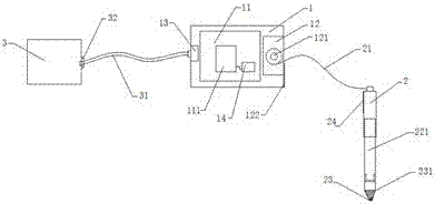
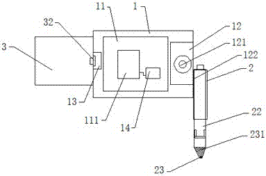
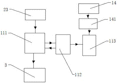
[0017] see Figure 1-Figure 3 , an automatic geotechnical detection system, including a control box 1, a detection rod 2 and a printing device 3, the inside of the control box 1 is provided with a controller 11, the side of the control box 1 is provided with a wire receiving groove 12, the The output end of the controller 11 is connected with a signal receiving line 21 , and the wire receiving slot 12 is provided with a winding shaft 121 inside, and the signal receiving line 21 is wound with the winding shaft 121 . The signal receiving line 21 is retracted according to the required length through the winding shaft 121, so as to improve the uniformity of the detection position when the detection rod 2 detects rocks. The output end of the signal receiving line 21 passes through the wire receiving groove 12 and is fixedly connected to the end of the detection rod 2. An extension rod 22 is ...


PUM


Abstract

The invention discloses an automatic rock soil detecting system. The automatic rock soil detecting system comprises a control box, a detecting rod and a printing device, wherein a controller is arranged in the control box; a wire collecting rove is formed in the side edge of the control box; the output end of the controller is connected with a signal receiving wire; the output end of the signal receiving wire penetrates through the wire collecting groove and is fixedly connected with the tail end of the detecting rod; a detecting probe is arranged on the output end of the detecting rod; the output end of the detecting probe is electrically connected with the input end of the controller; the output end of the controller is connected with a signal output wire and is electrically connected with the input end of the printing device through the signal output wire; a CPU (Central Processing Unit) and a wireless network device are arranged in the controller. According to the automatic rock soil detecting system disclosed by the invention, the structure is simple, the use is convenient, the analysis accuracy of rock detecting data can be effectively increased, and the data analysis efficiency can be increased.

Description

technical field [0001] The invention relates to the technical field of rock engineering, in particular to an automatic rock and soil detection system. Background technique [0002] With the rapid development of modern construction, all kinds of projects are changing with each passing day, such as heavy factories, high-rise buildings, major water conservancy hubs, dangerous railways, bridges and tunnels, and various developments in order to seek resources from the ocean and strive for space underground. Sexual engineering, etc., are all closely related to the rock and earth formations on which they depend. The success of various projects depends to a large extent on whether the rock and soil can provide sufficient bearing capacity to ensure that the building does not have excessive or uneven settlement that affects its safety and normal use, as well as horizontal displacement and stability. Or various forms of geotechnical stress. In order to ensure the safety of various pr...

Claims


Application Information

Patent Timeline
Patent Type & Authority Applications(China)
IPC IPC(8): G01N33/24
CPCG01N33/24
Inventor 洪海沈莉李娟
Owner JIANGSU DONGHENG DADI ENG TECH
Learn More