
Driving circuit and liquid crystal display device

A technology of drive circuit and gate drive circuit, which is applied to static indicators, instruments, etc., can solve the problems of constant power consumption for display and cannot meet the requirements of low power consumption of liquid crystal displays, and achieve the effect of saving power consumption

Active Publication Date: 2017-12-08
KUSN INFOVISION OPTOELECTRONICS
View PDF8 Cites 2 Cited by
  • Summary
  • Abstract
  • Description
  • Claims
  • Application Information

AI Technical Summary

Problems solved by technology

However, no matter what kind of picture mode is displayed by this display device, the power consumption of the display is always the same, which cannot meet people's requirements for low power consumption of liquid crystal displays.

Method used


Image

  • Driving circuit and liquid crystal display device
  • Driving circuit and liquid crystal display device
  • Driving circuit and liquid crystal display device

Examples


no. 1 example

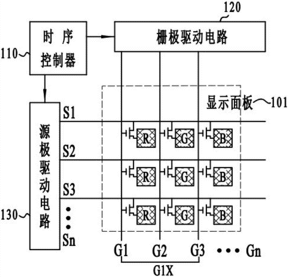
[0031] Such as figure 2 Shown is a schematic structural diagram of the driving circuit of the first embodiment of the present invention. Such as figure 2 As shown, the driving circuit provided by the present invention is used to drive the display panel 101 . The driving circuit includes a timing controller 110 , a gate driving circuit 120 and a source driving circuit 130 .

[0032] Wherein, the timing controller 110 is used for outputting the gate timing signal to the gate driving circuit 120 , and outputting the source timing signal to the source driving circuit 130 .

[0033] The gate drive circuit 120 includes a plurality of sub-gate drive circuits arranged in sequence, and each sub-gate drive circuit includes m gate drive units. Specifically, m may be equal to 3 or 4. In the first embodiment, m is equal to 3, and each The level gate driving unit is used to output the level gate driving signal Gn (n is equal to 1, 2, 3...N) to the corresponding sub-pixel according to t...

no. 2 example

[0060] Such as Figure 9 Shown is a schematic structural diagram of the driving circuit of the second embodiment of the present invention. Such as Figure 9 As shown, the driving circuit provided by the present invention is used to drive the display panel 101 . The driving circuit includes a timing controller 110 , a gate driving circuit 120 and a source driving circuit 130 .

[0061] Wherein, the timing controller 110 is used for outputting the gate timing signal to the gate driving circuit 120 , and outputting the source timing signal to the source driving circuit 130 .

[0062] The gate drive circuit 120 includes a plurality of sub-gate drive circuits arranged in sequence, and each sub-gate drive circuit includes 4 (m is equal to 4) gate drive units, and each level of gate drive units is used to output the current sequence according to the gate timing signal. level gate drive signal Gn (n is equal to 1, 2, 3...N) to the corresponding sub-pixel, wherein, N is an integer g...


PUM


Abstract

The present invention discloses a driving circuit and a liquid crystal display device. The driving circuit is provided with a timing controller, a gate driving circuit and a source driving circuit. When a power saving display mode is started, gate driving signals output by each gate driving unit in the same sub-gate driving circuit are the same, and the number of times of switching of source driving signals output by the source driving circuit is 1 / m of the number of times of that in a color mode, so that the output signals of the gate driving circuit and the source driving circuit are changed to effectively save electricity and realize the switching of a display frame from a color mode to a black-and-white mode.

Description

technical field [0001] The invention relates to the field of display technology, in particular to a driving circuit and a liquid crystal display device. Background technique [0002] Liquid Crystal Display (LCD) has the advantages of good image quality, small size, light weight, low driving voltage, low power consumption, no radiation and relatively low manufacturing cost, and currently occupies a dominant position in the field of flat panel display. With the development and progress of liquid crystal display technology, people put forward higher requirements for the display quality, appearance design, high resolution, low power consumption and other characteristics of liquid crystal displays. [0003] figure 1 It is a schematic diagram of a partial equivalent circuit structure of an existing liquid crystal display device. The liquid crystal display device includes a display panel and a driving circuit. The display panel includes a plurality of pixel units, and each pixel...

Claims


Application Information

Patent Timeline
IPC IPC(8): G09G3/36
CPCG09G3/3674G09G3/3685
Inventor 吕晶陈龙蒋旭赵哲苏日嘎拉图王金烨
Owner KUSN INFOVISION OPTOELECTRONICS
Features
  • Generate Ideas
  • Intellectual Property
  • Life Sciences
  • Materials
  • Tech Scout
  • Unparalleled Data Quality
  • Higher Quality Content
  • 60% Fewer Hallucinations
Learn More