Connectors and Connector Systems

A connector and plug connector technology, which is applied in the direction of connection, parts of connection devices, contact parts, etc., to achieve the effect of maintaining impedance matching, preventing crosstalk, and expanding spacing

Active Publication Date: 2020-07-31
HIROSE ELECTRIC GROUP
View PDF11 Cites 0 Cited by
  • Summary
  • Abstract
  • Description
  • Claims
  • Application Information

AI Technical Summary

Problems solved by technology

Therefore, in a smaller connector, in the case of transmitting a higher frequency electrical signal, etc., due to the difference in the distance between the contact parts of adjacent terminals, it is not possible to sufficiently prevent the occurrence of crosstalk and other electrical adverse effects. interference caused by impedance matching

Method used


Image

  • Connectors and Connector Systems
  • Connectors and Connector Systems
  • Connectors and Connector Systems

Examples


Embodiment Construction

[0056] Embodiments of the present invention will be described below with reference to the drawings. In addition, in all the drawings for explaining the embodiment, in principle, the same reference numerals are attached to the same components, and repeated description thereof will be omitted. In addition, although each embodiment is demonstrated independently, it does not exclude that a connector is comprised by combining a mutual structural element.

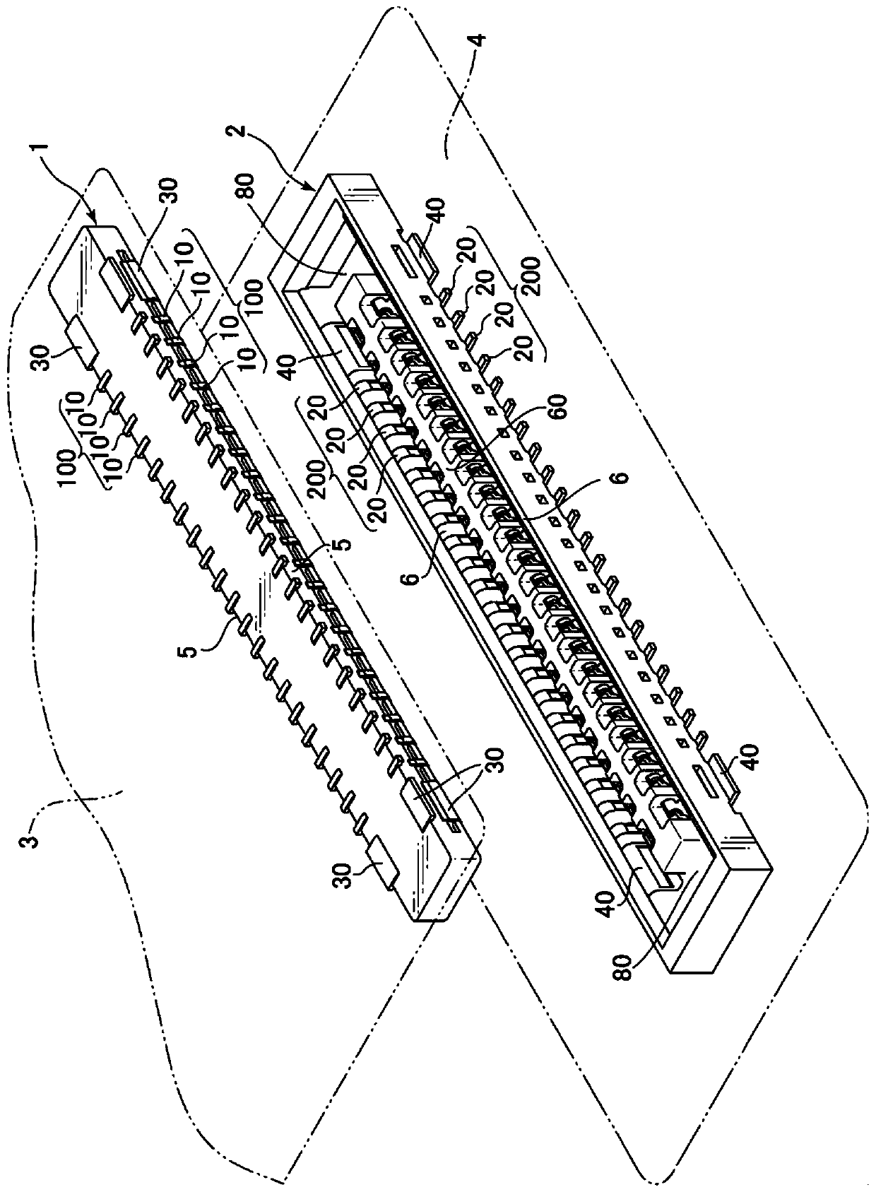
[0057] figure 1 It is a figure which shows the appearance of the connector system which consists of a plug connector and a receptacle connector concerning one Embodiment of this invention. This connector system can be used, for example, as an internal component in small electronic devices such as mobile phones, smartphones, digital cameras, and notebook personal computers. exist figure 1 In the plug connector 1 and the receptacle connector 2, part of the plurality of terminals in each of the plug connector 1 and the receptacle...


PUM


Abstract

In a connector with a structure that is more miniaturized and has a narrower terminal spacing (narrow pitch structure), in the case of transmitting higher-frequency electrical signals, etc., the spacing between the terminals is not constant, and it cannot be sufficiently connected. Prevent the interference of impedance matching caused by electrical negative effects such as crosstalk. The present invention provides a connector in which a plurality of terminals of the same shape are arranged at equal intervals along the longitudinal direction. The narrow-pitch structure can also keep the lateral width of the contact portion of each terminal and the interval between the contact portions of each terminal constant, and can expand the interval between the contact portions of each terminal, which can prevent terminals from being caused by mutual capacitance or induction. In the event of possible electrical negative effects such as crosstalk, the impedance matching can be properly maintained.

Description

technical field [0001] The present invention relates to a connector for connecting substrates and is suitable for high-speed transmission of electrical signals. Specifically, when a plurality of terminals of a connector are closely arranged at a narrow pitch, it is possible to prevent the occurrence of crosstalk that may occur between the terminals due to mutual capacitance or induction, and to maintain appropriate high-frequency characteristics such as impedance matching. The structure and arrangement of the terminals. Background technique [0002] A connector disclosed in JP-A-2005-149770 (Patent Document 1), for example, is known as a connector in which a plurality of terminals are aligned and held in a housing by integral molding or the like to connect substrates. The connectors described in Patent Document 1 include a plug connector and a receptacle connector (receptacle connector), and each connector includes a rectangular housing in which a plurality of terminals are...

Claims


Application Information

Patent Timeline
Patent Type & Authority Patents(China)
IPC IPC(8): H01R12/71H01R12/73
CPCH01R12/71H01R12/73H01R13/22H01R13/6471
Inventor 和田慎司
Owner HIROSE ELECTRIC GROUP
Why Eureka
Try Eureka