A resonant direct current line-to-line power flow controller

A power flow controller, resonant technology, applied in the direction of power transmission AC network, etc., to achieve the effect of high circuit efficiency

Active Publication Date: 2020-12-25
CHANGZHOU TIANMAN INTELLIGENT TECH
View PDF4 Cites 0 Cited by
  • Summary
  • Abstract
  • Description
  • Claims
  • Application Information

AI Technical Summary

Problems solved by technology

Since there is no reactive power, reactance and phase angle of AC, the DC transmission system can only adjust the transmission line resistance and DC voltage to control the DC power flow

Method used


Image

  • A resonant direct current line-to-line power flow controller
  • A resonant direct current line-to-line power flow controller
  • A resonant direct current line-to-line power flow controller

Examples


Embodiment Construction

[0016] The following will clearly and completely describe the technical solutions in the embodiments of the present invention. Obviously, the described embodiments are only some of the embodiments of the present invention, not all of them. Based on the implementation manners in the present invention, all other implementation manners obtained by persons of ordinary skill in the art without creative efforts fall within the protection scope of the present invention.

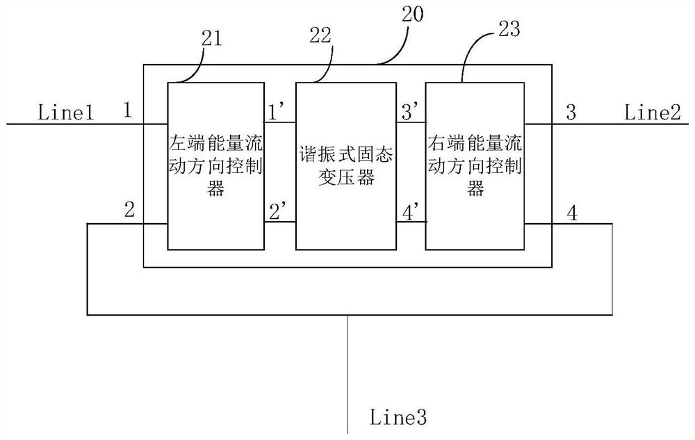
[0017] Such as figure 2 As shown, a resonant DC-line power flow controller 20 includes a left-end energy flow direction controller 21, a resonant solid-state transformer 22 and a right-end energy flow direction controller 23, and the input end of the left-end energy flow direction controller 21 are the first terminal 1 and the second terminal 2, and the output terminals of the energy flow direction controller 21 at the left end are terminal 1' and terminal 2', which are connected to the input terminals of the reson...


PUM


Abstract

The invention relates to a resonant DC interline power flow controller. The resonant DC interline power flow controller comprises a left-end energy flow direction controller, a resonant solid transformer and a right-end energy flow direction controller, wherein input ends of the left-end energy flow direction controller are a first terminal and a second terminal and an output end is connected with the resonant solid transformer; the output end of the resonant solid transformer is connected with the input end of the right-end energy flow direction controller and the output ends of the right-end energy flow direction controller are a third terminal and a fourth terminal; and the resonant solid transformer is a bidirectional resonant converter. The DC interline power flow controller is capable of achieving flow control of DC energy in any direction; isolation of a circuit is achieved by using the resonant solid transformer; and the circuit efficiency is improved.

Description

technical field [0001] The invention relates to the technical field of direct current transmission systems, in particular to a resonant direct current line-to-line power flow controller. Background technique [0002] The multi-terminal direct current transmission system is a direct current transmission system consisting of three or more converter stations connected in series, parallel or hybrid. It can realize multi-source power supply and multi-drop power reception. The operation of the system is more economical and flexible, and it is one of the effective technical means to solve the problems of large-scale renewable energy grid integration, large-capacity long-distance power transmission and shortage of transmission corridors that my country is currently facing. The equivalent circuit of a typical ring network three-terminal DC transmission system is as follows: figure 1 As shown in , it is assumed that converter station 1 and converter station 2 are the converter station...

Claims


Application Information

Patent Timeline
Patent Type & Authority Patents(China)
IPC IPC(8): H02J3/36
CPCH02J3/36Y02E60/60
Inventor 曼苏乐
Owner CHANGZHOU TIANMAN INTELLIGENT TECH
Why Eureka
Try Eureka