Intermediate case of engine

An engine and intermediary technology, which is applied in the direction of engine components, machines/engines, liquid fuel engines, etc., can solve the problems of design difficulty and cost increase, limited space of support plates, and increase the complexity of airfoil structure, etc., to improve airflow distribution The effect of circumferential unevenness

Active Publication Date: 2017-03-08
AECC COMML AIRCRAFT ENGINE CO LTD
View PDF7 Cites 0 Cited by
  • Summary
  • Abstract
  • Description
  • Claims
  • Application Information

AI Technical Summary

Problems solved by technology

[0005] In the design of some aircraft wings, in order to deal with the flow problem at the tail of the airfoil, some special structures and methods have been introduced, such as active or passive flow control technologies such as adjustable trailing edge and trailing edge blowing and suction, but these technologies are often While increasing the structural complexity of the airfoil itself, it is also necessary to introduce more complex peripheral equipment and additional technologies such as a flow monitoring system, a control system for adjusting or blowing air, and an air source system.
When applied to the internal flow control of the intermediate casing, the number of support plates is large and the space is limited, the complexity of these peripheral auxiliary equipment and technologies will increase, and the design difficulty and cost will increase when used as an engineering application. Reliability issues protrude

Method used


Image

  • Intermediate case of engine
  • Intermediate case of engine
  • Intermediate case of engine

Examples


Embodiment Construction

[0039] The present invention will be described in detail below in conjunction with the accompanying drawings and specific embodiments. Note that the aspects described below in conjunction with the drawings and specific embodiments are only exemplary, and should not be construed as limiting the protection scope of the present invention.

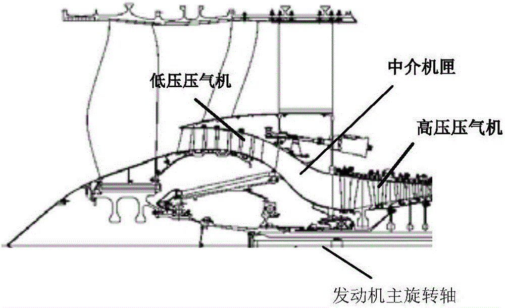
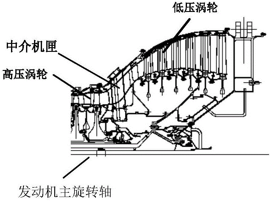
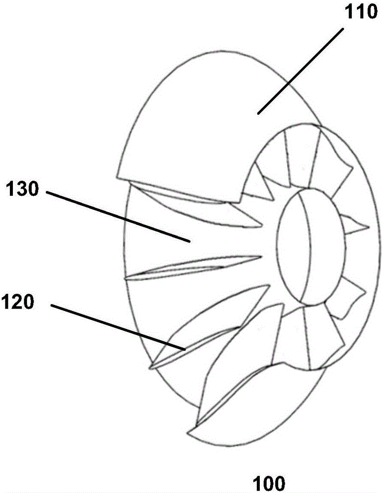
[0040] figure 2 is a schematic diagram showing the structure of the interposer casing 200 according to one aspect of the present invention. figure 2 Only one support plate 210 of the numerous support plates distributed along the circumferential direction of the main engine rotating shaft 130 of the intermediate casing 200 is shown in FIG. Also, for clarity, figure 2 The outer wall and inner wall of the intermediary casing 200 are also omitted in the figure, and a support plate 210 supported between them is directly shown. in addition, figure 2 Also shown in the engine main axis of rotation 230 . From Figure 1C The schematic diagram ...


PUM


Abstract

The invention provides an intermediate case of an engine. The intermediate case comprises an outer wall, an inner wall and a plurality of supporting plates supported between the outer wall and the inner wall, each supporting plate forms a hollow structure through two bent surfaces of a blade, wherein a cross flow fan is arranged on the tail position inside at least one of the supporting plates, the cross flow fan comprises a driving shaft extending along the height direction of the supporting plate and fan blades circumferentially distributed along the length of the driving shaft, and the two surfaces of the blade of the supporting plate with the cross flow fan are provided with an air inlet in the position of the cross flow fan and an air outlet in the tail end of a tail part.

Description

technical field [0001] The invention relates to engine technology, in particular to an engine intermediate casing. Background technique [0002] The intermediate casing of the aero-engine is used to undertake the airflow transition between the upstream and downstream high and low pressure components, and in order to meet the load-bearing requirements of the structural equipment and strength, there are generally multiple support plates in the intermediate casing. There are drive shafts and pipelines passing through the intermediary casing. Figure 1A and Figure 1B An intermediary casing between the low-pressure compressor and the high-pressure compressor, and an intermediary casing between the high-pressure turbine and the low-pressure turbine are shown, respectively. Figure 1C The structure of a typical intermediate casing is shown. Such as Figure 1C It can be seen that a typical intermediary casing 100 includes an outer wall 110 and an inner wall 130, and the outer wa...

Claims


Application Information

Patent Timeline
IPC IPC(8): F01D9/02F01D15/08F04D25/08F04D29/26F04D29/40
Inventor 李游童辉曹传军李斌
Owner AECC COMML AIRCRAFT ENGINE CO LTD
Why Eureka
Try Eureka