Semi-closed permanent magnet motor cooling system

A permanent magnet motor and cooling system technology, applied in cooling/ventilation devices, electromechanical devices, electrical components, etc., to achieve the effect of saving system energy consumption, high reliability design, and increasing structural complexity

Active Publication Date: 2020-11-17
INST OF ELECTRICAL ENG CHINESE ACAD OF SCI
View PDF6 Cites 4 Cited by
  • Summary
  • Abstract
  • Description
  • Claims
  • Application Information

AI Technical Summary

Problems solved by technology

[0004] In order to solve the above-mentioned problems in the prior art, that is, in order to solve the problem that the motor cannot not only ensure the cooling effect but also ensure that the strong magnetic rotor of the motor does not enter the iron filings and dust in the harsh operating environment, the present invention provides a semi-closed The permanent magnet motor cooling system includes a stator, a rotor, a rotating shaft and a casing. The stator includes a stator core and a stator winding. The stator winding is arranged at both ends of the stator core, and the stator core is fixed on the inner wall of the casing. The system It also includes an air inlet hole, an air outlet hole and a rotor sleeve structure, and the rotor sleeve structure is sleeved on the outside of the rotor to isolate the rotor from the stator; the air inlet hole, the outlet The air holes are arranged through the first end cover and the second end cover of the casing respectively, and the air inlet hole and the air outlet hole are located between the rotor sleeve structure and the casing; the air inlet hole, The air outlet hole and the communication gap between them constitute a cooling channel;

Method used


Image

  • Semi-closed permanent magnet motor cooling system
  • Semi-closed permanent magnet motor cooling system
  • Semi-closed permanent magnet motor cooling system

Examples


Embodiment 1

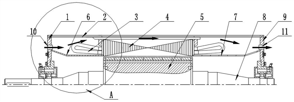
[0049] Refer to attached figure 1 , which is a cross-sectional schematic diagram of a specific embodiment of the semi-closed permanent magnet motor cooling system of the present invention, the cooling system includes a stator, a rotor 5, a rotating shaft 8 and a casing 2, wherein the stator includes a stator core 4 . Stator winding 3. The stator winding is arranged at both ends of the stator core, and the stator core is fixed on the inner wall of the casing. The system also includes the air inlet 10, the air outlet 11 and the rotor sleeve structure. The rotor sleeve structure is set On the outside of the rotor 5, to isolate the rotor and the stator; the air inlet hole and the air outlet hole respectively pass through the first end cover 1 and the second end cover 9 of the casing 2, and the air inlet hole 10 and the air outlet hole 11 Located between the rotor sleeve structure and the casing 2, it is used to realize the air guide of the externally installed air cooling device o...

Embodiment 2

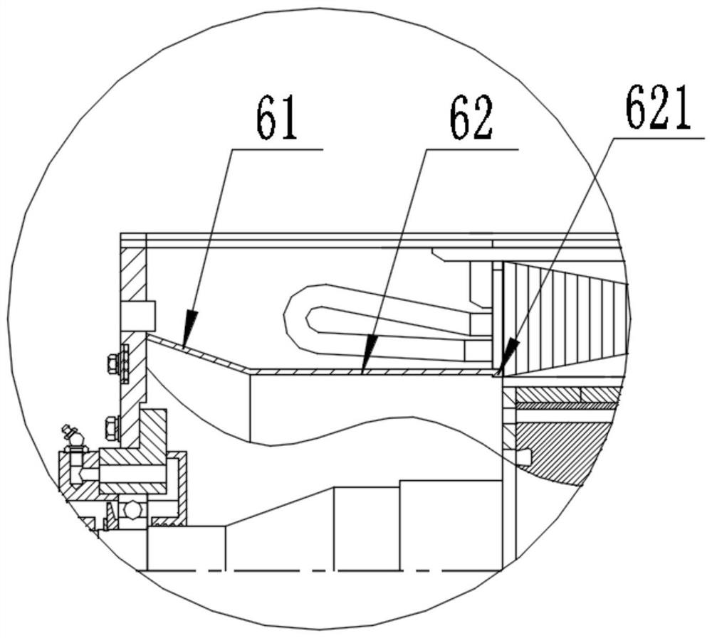
[0057] Refer to attached image 3 , shown as figure 1 The structural diagram of the second specific embodiment of the partial enlarged view in A, on the basis of the first embodiment, the end of the second structure 62 away from the first structure 61 is provided with a second protrusion 621, and the second protrusion is far away from the first structure 61. The side of a structure is arranged parallel to the surface to be connected to the first end of the stator core, and the second protrusion is arranged perpendicular to the axis of the rotating shaft, that is, the second protrusion in this embodiment protrudes inward relative to the second structure out of the setting to increase the contact area with the first end of the stator core; the first tubular structure is bonded to the first end cover through the end of the first structure away from the second end cover, and is close to the stator core through the second protrusion One side is bonded to the first end of the stato...

Embodiment 3

[0060] Refer to attached Figure 4 , shown as figure 1 The structural diagram of the third specific embodiment of the partial enlarged view of A, on the basis of the second embodiment, the end of the first structure away from the second structure is provided with a first protrusion 611, and the first protrusion 611 is far away from the second The side part of the structure is arranged parallel to the first end cover, and the first protrusion is arranged perpendicular to the axis of the rotating shaft, that is, the first protrusion in this embodiment protrudes outward relative to the first structure, increasing the distance from the first end cap. The contact area of ​​an end cover; the first tubular structure is bonded to the first end cover through the first protrusion 611 provided on the first structure, and the first end of the stator core is connected to the first end of the stator core through the second protrusion provided on the second structure (that is, the tooth por...


PUM


Abstract

The invention belongs to the technical field of motor cooling systems, and provides a semi-closed permanent magnet motor cooling system in order to solve the problems that the cooling effect cannot beguaranteed, and no scrap iron or dust enters a strong magnetic rotor of a motor under the condition that the operation environment of the motor is severe. The system comprises a rotor, a rotating shaft, a casing, a stator core, a stator winding, an air inlet hole, an air outlet hole and a rotor sleeve structure, and the rotor sleeve structure sleeves the rotor to isolate the rotor from a stator;and the air inlet hole and the air outlet hole separately penetrate through an end cover arranged on the casing. In the working process, the external cooling air is guided in through the air inlet hole, flows through the stator winding at the end part of one side of the motor, the cooling channel on the stator iron core and the stator winding at the end part of the other side of the motor and thenflows out through the air outlet hole so as to cool the semi-closed permanent magnet motor. According to the present invention, foreign matters can be prevented from entering the rotor, and the cooling effect of the motor is not affected.

Description

technical field [0001] The invention belongs to the technical field of motor cooling systems, and in particular relates to a semi-closed permanent magnet motor cooling system. Background technique [0002] The cooling methods of conventional permanent magnet motors are mainly divided into direct cooling (internal cooling) and indirect cooling (external cooling), and the commonly used cooling methods mainly include: 1) surface cooling: the cooling area of ​​this cooling method is to use the motor casing surface, to increase the heat dissipation area, and cooling fins are commonly used on the surface of the casing. This cooling method has a simple structure and is suitable for small and medium-sized enclosed motors, but its cooling effect is limited; 2) Open ventilation cooling: This cooling method uses the cooling medium (generally air) directly into the motor, and the medium absorbs energy and discharges it to the surrounding environment. This cooling method is suitable for ...

Claims


Application Information

Patent Timeline
Patent Type & Authority Applications(China)
IPC IPC(8): H02K5/20H02K9/06H02K1/20H02K1/32H02K5/10
CPCH02K5/20
Inventor 熊斌阮琳崔刚
Owner INST OF ELECTRICAL ENG CHINESE ACAD OF SCI
Why Eureka
Try Eureka