Heat storage device

a technology of storage device and heat storage device, which is applied in the direction of liquid fuel feeder, machine/engine, mechanical apparatus, etc., can solve the problems of increasing the bulk of the device overall and the complexity of the structure, and achieve the effect of compact and simple structur

Inactive Publication Date: 2019-01-08
TOYOTA CENT RES & DEV LAB INC
View PDF15 Cites 4 Cited by
  • Summary
  • Abstract
  • Description
  • Claims
  • Application Information

AI Technical Summary

Benefits of technology

[0006]In a heat transport device with a structure such as that described above, one of the adsorption vessels is utilized as a heat storage vessel and emits ammonia during heat storage, and the other adsorption vessel holds the emitted ammonia. Equipping such a structure with plural adsorption vessels leads to an increase in bulk of the device overall, and leads to an increase in complexity of the structure.
[0007]An exemplary embodiment of technology disclosed herein provides a heat storage device with a compact and simple structure.
[0010]Thus by utilizing the fuel held in the fuel tank as a reaction medium for the heat storage material, there is no need to provide an additional member to supply a reaction medium to the heat storage vessel. Moreover, the fuel held in the fuel tank is also fuel to be combusted by the engine, and fuel desorbed from the heat storage material is combusted in the engine, so there is also no need for a member to hold the fuel desorbed from the heat storage material. A heat storage device having a compact and simple structure is thereby obtained.
[0014]Namely, heat of the engine cooling water is employed in the heat storage vessel when the fuel gas is desorbed and heat is stored, thereby enabling efficient heat storage.
[0016]Heat can be efficiently dissipated from the adsorbent by utilizing adsorption of fuel gas to the adsorbent.
[0023]Due to adopting the above configurations, the technology disclosed herein obtains a heat storage device having a compact and simple structure.

Problems solved by technology

Equipping such a structure with plural adsorption vessels leads to an increase in bulk of the device overall, and leads to an increase in complexity of the structure.

Method used


Image

  • Heat storage device
  • Heat storage device
  • Heat storage device

Examples


Embodiment Construction

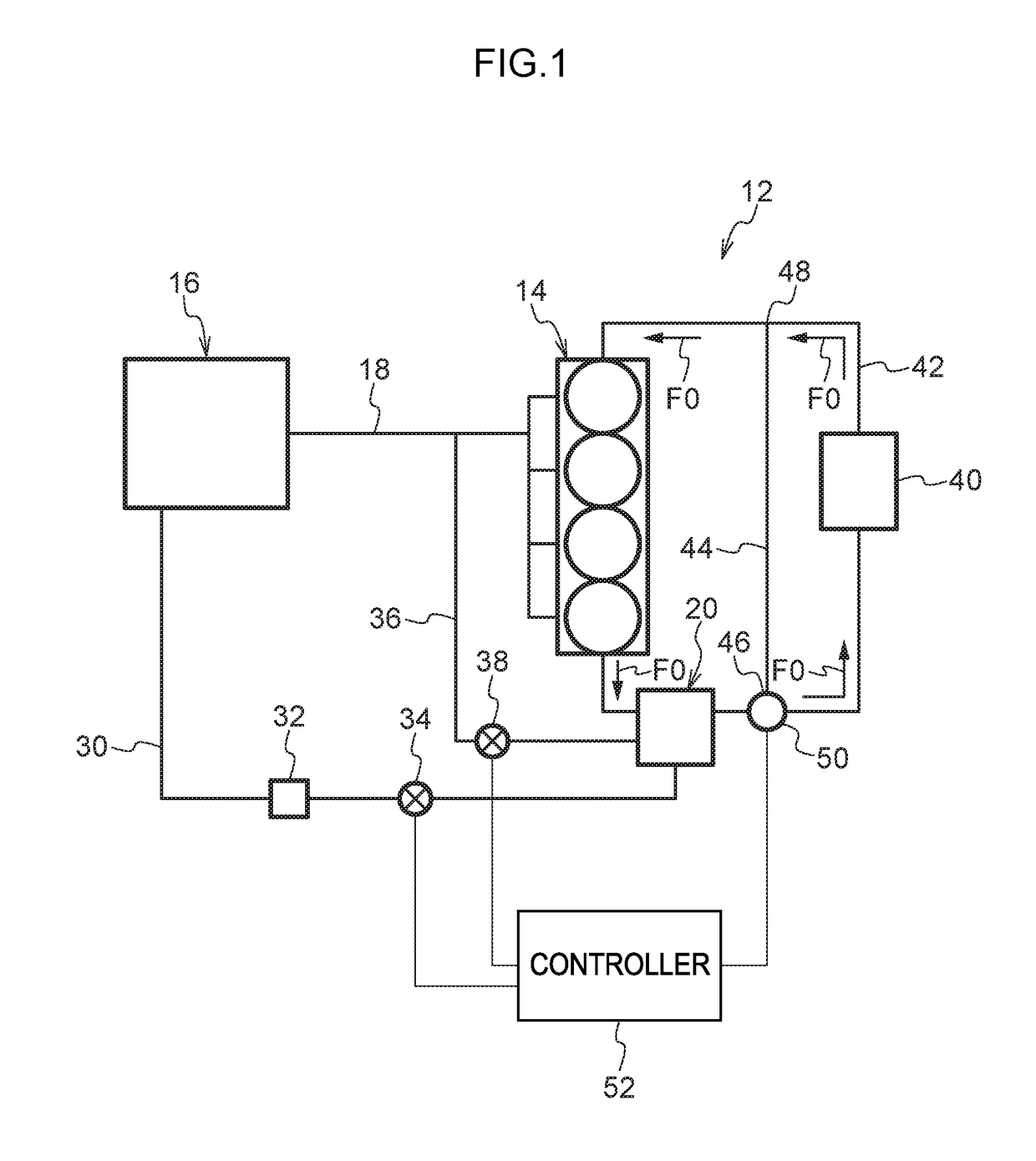
[0033]FIG. 1 illustrates a heat storage device 12 of a first exemplary embodiment according to technology disclosed herein, together with an automobile engine 14 and the like.

[0034]As fuel, the engine 14 of the first exemplary embodiment employs compressed natural gas (CNG) as an example of a gas phase fuel. An example of compressed natural gas is gas in which the main component is methane. A fuel tank 16 that holds the compressed natural gas, and the engine 14, are connected together by a feed pipe 18. The compressed natural gas inside the fuel tank 16 is supplied to the engine 14 through the feed pipe 18.

[0035]The heat storage device 12 includes a heat storage vessel 20. The fuel tank 16 and the heat storage vessel 20 are connected together by a first pipe 30. The compressed natural gas inside the fuel tank 16 is fed to the heat storage vessel 20 through the first pipe 30.

[0036]A pressure regulation valve 32 and an open / close valve 34 are provided on the first pipe 30. The pressur...


PUM


Abstract

A heat storage device including a fuel tank holding a fuel to be combusted in an engine, a heat storage vessel including a heat storage material that dissipates heat by adsorbing or chemically reacting with a fuel gas that has been vaporized, and that stores heat by desorption by heating the fuel gas, a first flow path to feed the fuel from the fuel tank to the heat storage vessel, and a second flow path to feed the fuel gas from the heat storage vessel to the engine.

Description

CROSS-REFERENCE TO RELATED APPLICATION[0001]This application claims priority under 35 USC 119 from Japanese Patent Application No. 2016-011655 filed on Jan. 25, 2016, the disclosure of which is incorporated by reference herein in its entirety.BACKGROUND[0002]Technical Field[0003]Preferred embodiments relate to a heat storage device.[0004]Related Art[0005]There are heat transport devices provided with two or more adsorption vessels that store heat by desorption of ammonia and dissipate heat by adsorption of ammonia, and employ a difference in ammonia pressure arising between the adsorption vessels to transport the ammonia from one of the adsorption vessels to the other adsorption vessel (see, for example, Japanese Patent Application Laid-Open (JP-A) No. 2015-183984).SUMMARY[0006]In a heat transport device with a structure such as that described above, one of the adsorption vessels is utilized as a heat storage vessel and emits ammonia during heat storage, and the other adsorption ves...

Claims


Application Information

Patent Timeline
Patent Type & Authority Patents(United States)
IPC IPC(8): F02B43/02F02B43/08F02M37/00F02M25/08F02M37/22
CPCF02B43/08F02M25/08F02M37/0023F02M37/30F02M37/0064F02B43/02Y02T10/32Y02T10/30
Inventor YAMAUCHI, TAKAFUMIHIROTA, YASUKI
Owner TOYOTA CENT RES & DEV LAB INC
Why Eureka
Try Eureka