Detachable cooling device module

A cooling device and detachable technology, applied to locomotives and other directions, can solve problems such as inconvenient loading and unloading, difficult maintenance, and inconvenient passage of personnel, and achieve the effect of convenient installation and disassembly, solving the inconvenience of installation and disassembly, and changing the appearance and reasonableness

Inactive Publication Date: 2017-12-12
CRRC DALIAN CO LTD
View PDF6 Cites 0 Cited by
  • Summary
  • Abstract
  • Description
  • Claims
  • Application Information

AI Technical Summary

Problems solved by technology

When installing large parts in the cooling chamber (such as air compressors, etc.), they can only be hoisted in through the side wall door of the car body, which is inconvenient for loading and unloading and difficult for maintenance
[0003] The structures on both sides of the cooling device exceed the limit of the steel structure of the car body and are located above the car body walking platform, making it inconvenient for personnel to pass through

Method used


Image

  • Detachable cooling device module
  • Detachable cooling device module

Examples


Embodiment Construction

[0011] The present invention will be further described below in conjunction with the drawings.

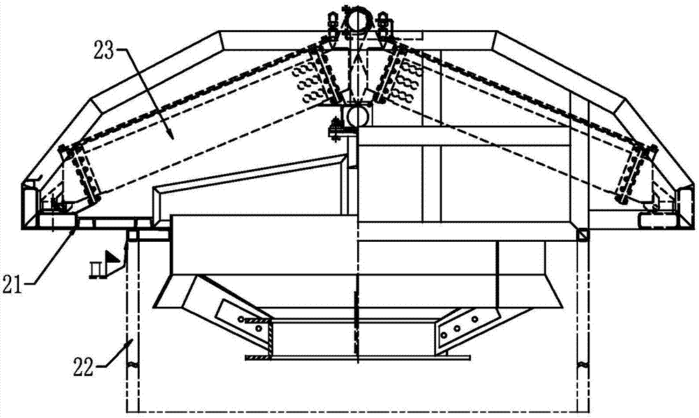
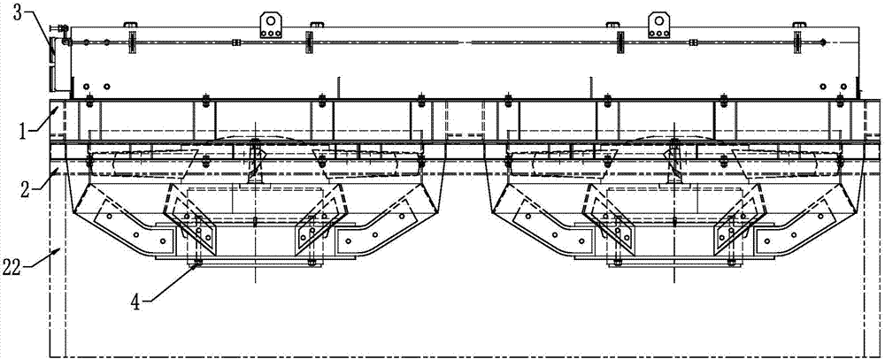
[0012] The invention adopts the design of separated cooling steel structure, the large multi-process radiator replaces the old radiator, the radiator 3, the fan motor unit 4 and the cooling steel structure two 2 are assembled in advance to realize the modular design; the new multi-process large radiator replaces The original single-section large radiator solves the problem of difficulty in passing the platform personnel.

[0013] The present invention designs a new type of cooling steel structure to replace the original welded cooling steel structure. The cooling steel structure of the present invention is divided into cooling steel structure 1 and cooling steel structure 2. The cooling steel structure 1 and the car body are welded The cooling steel structure 2 and the radiator 3, and the fan motor unit 4 are assembled into modules in advance, and then installed in the vehicle. The modu...


PUM


Description

Technical field [0001] The invention relates to the technical field of locomotive cooling devices. Background technique [0002] During the operation of the locomotive, the original design of the locomotive was to use welding between the cooling steel structure and the car body, forming a completely enclosed space that cannot be disassembled. When installing large parts in the cooling chamber (such as air compressors, etc.), they can only be hoisted in through the side wall door of the vehicle body, which is inconvenient for loading and unloading and difficult to maintain. [0003] The structure on both sides of the cooling device exceeds the limit of the steel structure of the car body and is located above the platform of the car body, which is not convenient for people to pass. See for details figure 1 . Summary of the invention [0004] The technical problem solved by the present invention is to provide a detachable cooling device module with simple structure and convenient dis...

Claims


Application Information

Patent Timeline
Patent Type & Authority Applications(China)
IPC IPC(8): B61C17/04
CPCB61C17/04
Inventor 赵俊勇董志忠王帅孙弘谋于海闫冰
Owner CRRC DALIAN CO LTD
Why Eureka
Try Eureka