
Undercarriage control actuating cylinder hydraulic control valve

The technology of hydraulic control valve and actuator is applied in the field of aircraft landing gear, which can solve the problems of increased weight, difficult structural layout, and reduced reliability, and achieves the effects of improving reliability, improving reliability and safety, and saving space.

Active Publication Date: 2017-12-12
LANDING GEAR ADVANCED MFG
View PDF3 Cites 8 Cited by
  • Summary
  • Abstract
  • Description
  • Claims
  • Application Information

AI Technical Summary

Problems solved by technology

[0005] The control valve of the existing landing gear retractable cylinder is generally completed by multiple independent hydraulic control components when realizing the functions of hydraulic lock, oil differential compensation, oil circuit pulse, and thermal safety protection, which will increase the hydraulic pressure. The complexity of the system and the design of the retractable mechanism of the landing gear will also bring about problems such as difficulties in the layout of related structures, increased weight, and reduced reliability.

Method used


Image

  • Undercarriage control actuating cylinder hydraulic control valve
  • Undercarriage control actuating cylinder hydraulic control valve
  • Undercarriage control actuating cylinder hydraulic control valve

Examples


Embodiment Construction

[0038] For the convenience of description, the description of the relative positional relationship of each component (such as: left, right, etc.) is described according to the layout direction of the drawings in the specification, and does not limit the structure of this patent.

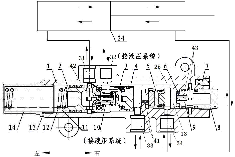
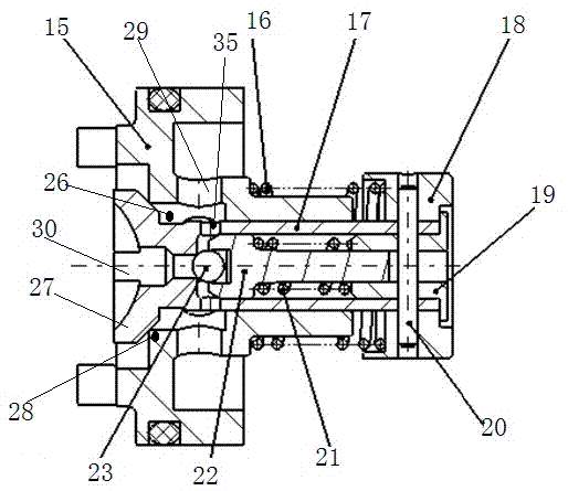
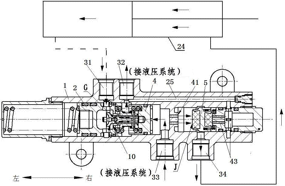
[0039] Such as Figure 1~6 As shown, a hydraulic control valve for retracting and extending the landing gear includes a valve body 1, and the valve body 1 is provided with a left chamber 11, a right chamber 13, and a first oil passage connecting the left and right chambers. 41.

[0040] A buffer piston 2 and a traveling piston 4 are arranged at intervals from left to right in the left chamber 11 , and a thermal safety valve 10 is arranged between the buffer piston 2 and the traveling piston 4 .

[0041] The left end of the valve body 1 is provided with a hollow spring sleeve 14 . A first spring 12 is provided between the left end of the buffer piston 2 and the left end surface of the valve body 1 ....


PUM


Abstract

The invention discloses an undercarriage control actuating cylinder hydraulic control valve. The undercarriage control actuating cylinder hydraulic control valve comprises a valve body, a first pipe nozzle, a fourth pipe nozzle, a second pipe nozzle and a third pipe nozzle are formed in the valve body, the first pipe nozzle and the fourth pipe nozzle communicate with an actuating cylinder rodless cavity and an actuating cylinder rod cavity, the second pipe nozzle and the third pipe nozzle communicate with a hydraulic system, a buffer piston and a floating piston are arranged in a left cavity in a spaced manner, a thermal safety valve is arranged between the buffer piston and the floating piston, a second oil path is arranged on the buffer piston, a cavity between the buffer piston and the floating piston and the second oil path communicate and are throttled through the thermal safety valve, and an oil compensation channel communicating with the second pipe nozzle is arranged in the valve body; a liquid control valve and a seal base are arranged in a right cavity in a spaced manner. The hydraulic control valve enables hydraulic lock, oil differential compensation, oil path pulsation, and thermal safety protection functions to be integrated in one component, opening and closing of a hydraulic lock, conversion of the oil compensation function and opening of the oil path pulsation, and thermal safety protection can be automatically coordinated, and finally, through control over the actuating cylinder, undercarriage bearing, rapid putting down, oil path pulsation, and heat safety protection functions are achieved.

Description

technical field [0001] The invention belongs to the technology of aircraft landing gear, and in particular relates to a hydraulic control valve for retracting and extending the cylinder of the landing gear. Background technique [0002] The functions of the landing gear retractable actuator are: 1. Under the action of hydraulic oil, it drives the landing gear to retract and lower; 2. Under the joint action of the hydraulic control valve and the built-in mechanical lock of the retractable actuator, it will The landing gear is locked in the stowed or extended position, allowing the landing gear to carry loads. [0003] With the continuous improvement of modern aircraft's requirements for the retractable mechanism and system reliability of the landing gear, it is generally necessary to install a hydraulic lock in addition to the mechanical lock in the retractable actuator, so that the mechanical lock and the hydraulic lock work at the same time, which can improve the landing ge...

Claims


Application Information

Patent Timeline
Patent Type & Authority Applications(China)
IPC IPC(8): F15B13/04F15B15/26
CPCF15B13/0402F15B15/26
Inventor 禹新鹏邓晓山金军慕建全吴林程国良关维鲁德发李兆昕
Owner LANDING GEAR ADVANCED MFG
Learn More