
Automatic pay-off machine for terminal crimping machine

A technology of terminal crimping machine and wire pay-off machine, which is applied in the direction of connection, line/collector parts, electrical components, etc. It can solve the problems of wires not meeting quality requirements, unstable wire feeding speed, inconsistent cutting length of wires, etc. , to achieve the effect of novel structure, stable line speed and high production quality

Active Publication Date: 2017-12-12
WEIHAI SUNFULL HANBECTHISTEM INTELLIGENT THERMO CONTROL
View PDF7 Cites 0 Cited by
  • Summary
  • Abstract
  • Description
  • Claims
  • Application Information

AI Technical Summary

Problems solved by technology

Although this structure can restrain the wires through the hole position adjustment conversion wheel during the conveying process, but in the terminal crimping process, due to the unstable wire feeding speed, the cutting length of the wires is inconsistent, resulting in the wires not meeting the quality requirements

Method used


Image

  • Automatic pay-off machine for terminal crimping machine
  • Automatic pay-off machine for terminal crimping machine
  • Automatic pay-off machine for terminal crimping machine

Examples


Embodiment Construction

[0017] The present invention will be described below in conjunction with the accompanying drawings and embodiments.

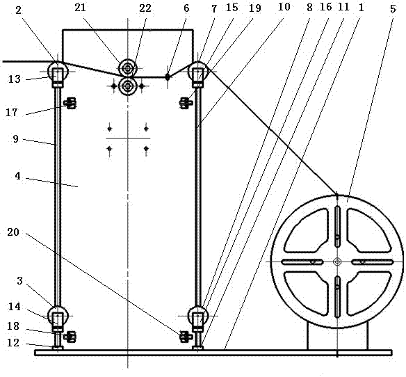
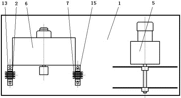
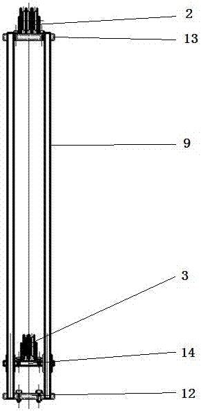
[0018] As shown in the accompanying drawings, an automatic pay-off machine for terminal crimping machine includes a base 1, a guide wheel 2 on the wire feeder, a lower guide wheel 3 on the wire feeder, a support 4 for the wire feeder machine and a wire pay-off machine 5. The wire machine support 4 is provided with a wire feeder 6, which is characterized in that it is provided with a guide wheel 7 on the pay-off line, a lower guide wheel 8 on the pay-off line, a wire-feeding slide bar 9, a pay-off slide bar 10, a pay-off slide bar seat 11, Wire feeding slider seat 12, wire feeding guide wheel seat 13, wire feeding lower guide wheel slide seat 14, pay-off line guide wheel seat 15, wire feeding lower guide wheel slide seat 16, wire feeder start proximity switch 17, wire feeder Stop proximity switch 18, pay-off machine start proximity switch 19, pay-off machine sto...


PUM


Abstract

The invention discloses an automatic pay-off machine for a terminal crimping machine. The pay-off machine comprises a base, a feeding upper guide wheel, a feeding lower guide wheel, a feeding machine support and a pay-off machine, wherein the feeding machine is arranged on the feeding machine support, the automatic pay-off machine is characterized in that a pay-off upper guide wheel, a pay-off lower guide wheel, a feeding sliding rod, a pay-off sliding rod, a pay-off sliding rod seat, a feeding sliding rod seat, a feeding upper guide wheel seat, a feeding lower guide wheel sliding seat, a pay-off upper guide wheel seat and a pay-off lower guide wheel sliding seat are arranged, an approximate switch is started by the feeding machine, the approximate switch is stopped by the feeding machine, the approximate switch is started by the pay-off machine, the approximate switch and a control system are stopped by the pay-off machine, the feeding sliding rod seat, the pay-off sliding rod seat, the feeding machine support and the pay-off machine are fixedly arranged on the base, the feeding sliding rod seat, the pay-off sliding rod seat and pay-off machine are sequentially arranged at intervals from left to right, and the feeding machine support is arranged at one side of the feeding sliding rod seat and one side of the pay-off sliding rod seat. With the adoption of the structure, the automatic pay-off machine has the advantages of a novel structure, stable linear speed, uniform speed, high production quality and the like.

Description

technical field [0001] The invention relates to the technical field of electric wire processing equipment, in particular to an automatic wire pay-off machine for terminal crimping machines. Background technique [0002] At present, when the wire terminal crimping machine with connecting metal sheet wires is produced, it is easy to cause messy wires, and because the diameters of the wires are different, it is difficult to find a way to solve the problems caused by wires of different specifications during processing. The problem of messy wires leads to a decrease in production efficiency and product quality, and it is generally difficult to accurately measure the length of the processed wires every day. It is very troublesome and unrealistic to measure the processed wire bundles. It is currently a major problem that plagues the production technicians of enterprises. [0003] In order to solve the above technical problems, CN 201774136 U discloses a utility model patent for a w...

Claims


Application Information

Patent Timeline
Patent Type & Authority Applications(China)
IPC IPC(8): H01R43/052
CPCH01R43/052
Inventor 王林政曹忠良刘昌庆王琳
Owner WEIHAI SUNFULL HANBECTHISTEM INTELLIGENT THERMO CONTROL
Learn More