Energy-saving method for collection equipment and collection equipment
A technology for collecting equipment and working status, which is applied in the energy-saving method of collecting equipment and in the field of collecting equipment, which can solve the problems of large actual power consumption, high hardware cost, and susceptibility to interference from environmental factors, so as to reduce equipment cost and maintenance cost, Effects of reducing communication abnormalities and realizing low-power operation
- Summary
- Abstract
- Description
- Claims
- Application Information
AI Technical Summary
Problems solved by technology
Method used
Image
Examples
no. 1 example
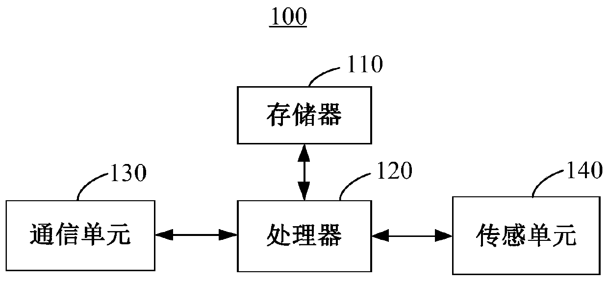
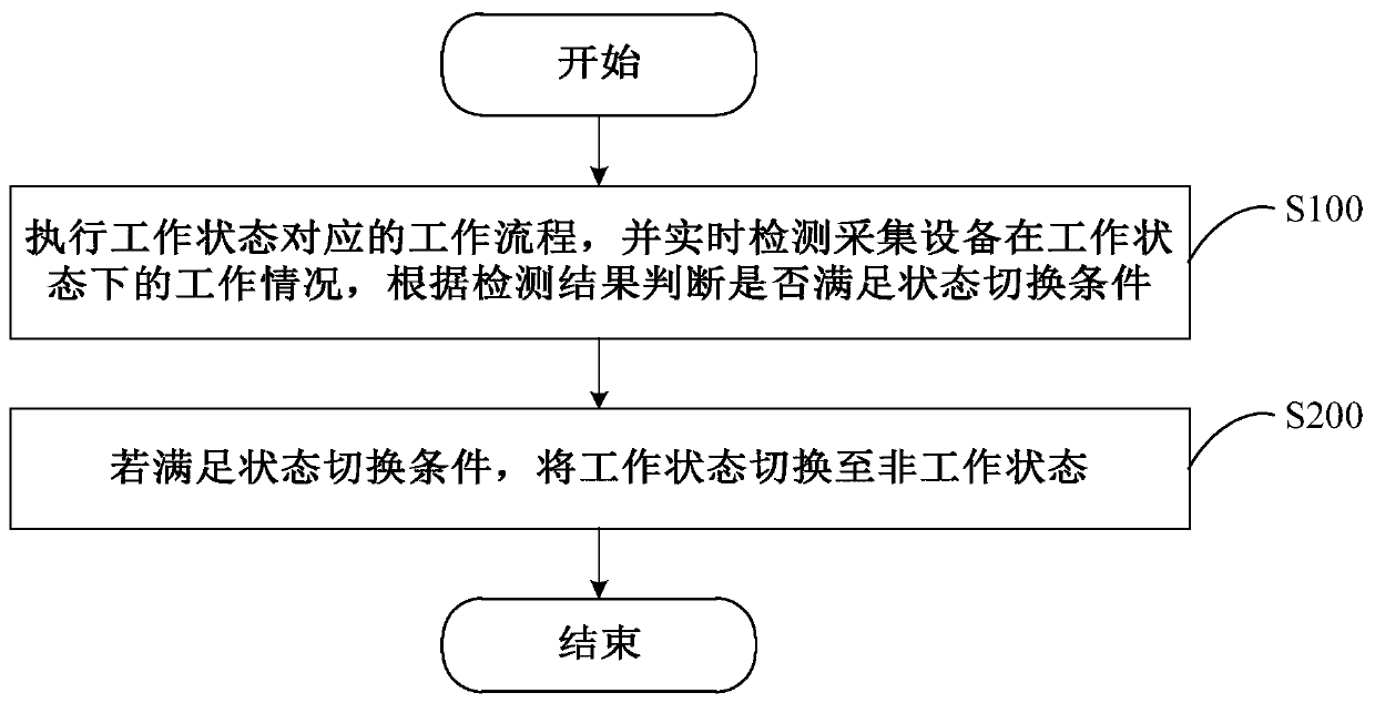
[0050] Please refer to image 3 , image 3 This is one of the flow charts of the steps of the energy saving method for a collection device provided by the first embodiment of the present invention. The method is applied to the collection device 100 communicatively connected to the monitoring host 300 . The collection device 100 includes different operating states, wherein the different operating states include: a working state and an abnormal working state. The specific process of the energy saving method for the collection device is described in detail below.
[0051] Step S100: Execute the work flow corresponding to the work state, and detect the work condition of the collection device 100 in the work state in real time, and judge whether the state switching condition is satisfied according to the detection result.
[0052] In step S200, if the state switching condition is satisfied, the working state is switched to the abnormal working state.
[0053] Please refer to ...
no. 2 example
[0107] Please refer to Figure 13 , Figure 13 This is a functional block diagram of the collection device 100 provided by the second embodiment of the present invention. The collection device 100 is connected in communication with the monitoring host 300, and the collection device 100 includes different operating states, wherein the different operating states include: a working state and an abnormal working state, and the abnormal working state includes: waiting In the wake-up state, the low battery state and the weak signal state, the collection device 100 includes: a working state running module 210 and an abnormal working state running module 220 .
[0108] The working state running module 210 is used for executing the working process corresponding to the working state, and detecting the working condition of the collecting device 100 in the working state in real time, and judging whether the state switching condition is satisfied according to the detection result.
[010...
no. 3 example
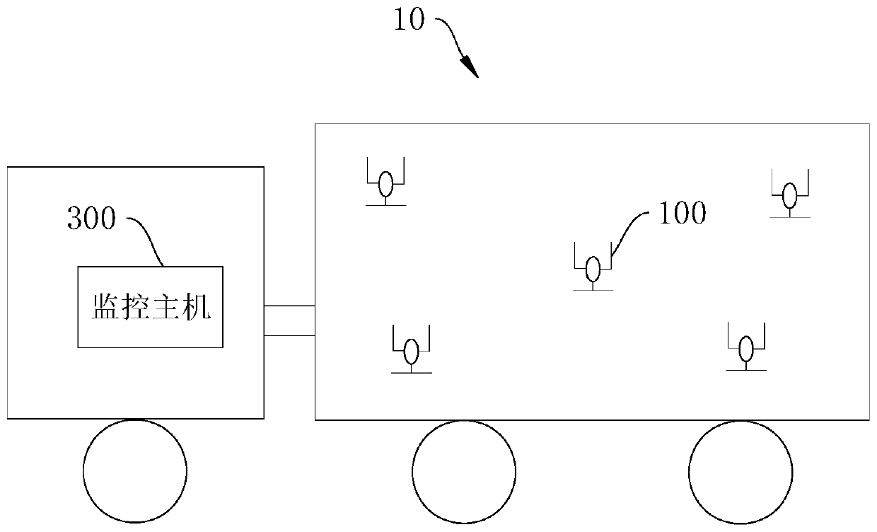
[0115] Please refer to Figure 14 , Figure 14 This is a flow chart of the steps of the energy saving method for a collection device provided by the third embodiment of the present invention. The energy saving method for the collection equipment is applied to the cold chain logistics vehicle 10 . The cold chain logistics vehicle 10 includes a monitoring host 300 and a plurality of collecting devices 100, and the plurality of collecting devices 100 and the monitoring host 300 are connected in communication through a wireless network. The energy saving method for a collection device provided by the third embodiment is a method executed when the current operating state of the collection device 100 is a weak signal state. The method includes:
[0116] In step 410, the monitoring host 300 selects a channel with a signal strength that meets the standard for switching according to the preset frequency hopping technology, so as to achieve rapid signal recovery and save energy consu...
PUM
 Abstract
Description
Claims
Application Information
 - R&D
- Intellectual Property
- Life Sciences
- Materials
- Tech Scout
- Unparalleled Data Quality
- Higher Quality Content
- 60% Fewer Hallucinations
Browse by: Latest US Patents, China's latest patents, Technical Efficacy Thesaurus, Application Domain, Technology Topic, Popular Technical Reports.
© 2025 PatSnap. All rights reserved.Legal|Privacy policy|Modern Slavery Act Transparency Statement|Sitemap|About US| Contact US: help@patsnap.com


