
Turning control method and device for mower

A technology for turning control, lawn mowers

Active Publication Date: 2017-12-15
POSITEC POWER TOOLS (SUZHOU) CO LTD
View PDF3 Cites 0 Cited by
  • Summary
  • Abstract
  • Description
  • Claims
  • Application Information

AI Technical Summary

Problems solved by technology

[0004] Therefore, the technical problem to be solved by the present invention is that lawnmowers in the prior art tend to wear turf when turning, thereby providing a lawnmower turning control method and device

Method used


Image

  • Turning control method and device for mower
  • Turning control method and device for mower

Examples


Embodiment 1

[0024] This embodiment provides a turning control method for a lawn mower, which is applied to a lawn mower, especially an intelligent lawn mower, such as figure 1 shown, including:

[0025] Step S101, determine the turning direction of the mower according to the turning control signal.

[0026] Step S102, adjusting the first motor of the lawn mower to a first rotational speed, and adjusting the second motor of the lawn mower to a second rotational speed, wherein the first motor is used to drive the turning inner wheel of the lawn mower to rotate, and the second The second motor is used to drive the turning outer wheel of the lawn mower to rotate. The turning inner wheel refers to the wheel on the side close to the turning direction when the lawn mower turns, and the turning outer wheel refers to the wheel on the side away from the turning direction when the lawn mower turns. The first rotational speed is greater than 0, and the second rotational speed is greater than the fir...

Embodiment 2

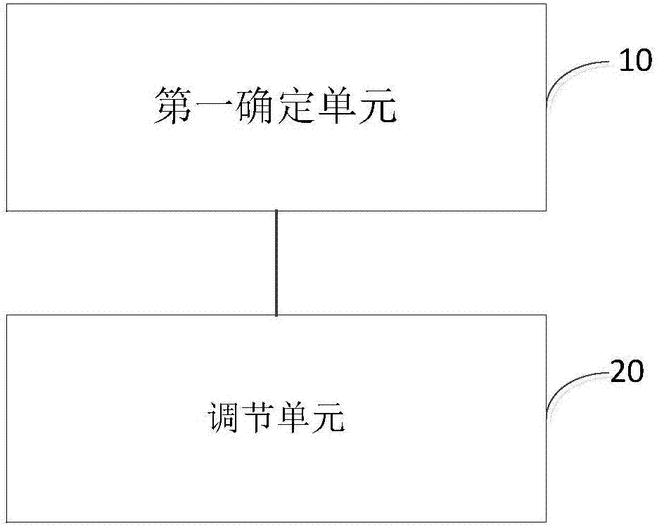
[0041] This embodiment provides a turning control device for a lawn mower, which can be used to implement the turning control method for a lawn mower according to Embodiment 1 of the present invention, such as figure 2 As shown, the device includes: a first determining unit 10 and an adjusting unit 20 .

[0042] The first determination unit 10 is used to determine the turning direction of the mower according to the turning control signal;

[0043] The adjustment unit 20 is used to adjust the first motor of the lawn mower from the current speed to the first speed, and adjust the second motor of the lawn mower from the current speed to the second speed, wherein the first motor is used to drive the lawn mower The turning inner wheel of the mower rotates, and the second motor is used to drive the turning outer wheel of the lawn mower to rotate. The turning outer wheel refers to the wheel on the side away from the turning direction when the lawn mower turns, and the turning inner ...


PUM


Abstract

The invention relates to the field of mowers, and particularly relates to a turning control method and device for a mower. The method comprises the following steps: determining a turning direction of the mower according to a turning control signal; and regulating a first motor of the mower to a first rotation speed, and regulating a second motor of the mower to a second rotation speed, wherein the first motor is used for driving inside turning wheels of the mower to rotate; the second motor is used for driving outside turning wheels of the mower to rotate; the inside turning wheels refer to the wheels close to the turning direction during the turning of the mower; the outside turning wheels refer to the wheels away from the turning direction during the turning of the mower; the first rotation speed is greater than 0; and the second rotation speed is greater than the first rotation speed. According to the invention, the problems of grass crushing, turf damage and the like easily caused by the situation that a turf is subjected to rolling abrasion when the rotation speed of the inside turning wheels is 0 in the turning process in the prior art are avoided.

Description

technical field [0001] The invention relates to the field of lawnmowers, in particular to a turning control method and device for a lawnmower. Background technique [0002] A lawn mower is a mechanical tool used to mow lawns, vegetation, etc. With the continuous advancement of computer technology and artificial intelligence technology, lawn mowers have also become more intelligent, and have begun to slowly enter people's lives. At present, some companies have developed smart lawn mowers that can automatically mow and charge the user's lawn without user intervention. Since this automatic mowing system does not need to invest in energy management after the initial setup, it frees users from boring and time-consuming housework such as cleaning and lawn maintenance, so it is very popular. [0003] For intelligent lawn mowers, how to automatically control them to complete mowing tasks, ensure mowing coverage, automatically return to charging, and turn control has always been a ...

Claims


Application Information

Patent Timeline
Patent Type & Authority Applications(China)
IPC IPC(8): A01D75/00A01B69/08
CPCA01B69/007A01D75/00
Inventor 周昶孙锡峰
Owner POSITEC POWER TOOLS (SUZHOU) CO LTD
Learn More