Biological fermentation tank

A biofermentation tank and tank technology, which is applied in the direction of bioreactor/fermenter combination, specific-purpose bioreactor/fermenter, biomass post-treatment, etc., can solve the problems of low fermentation efficiency, changes in the composition of fermentation products, fermentation The tank cannot observe the material reflection in real time and other problems, so as to achieve the effect of simple operation and reasonable structure design

Inactive Publication Date: 2017-12-15
李秋红
View PDF0 Cites 4 Cited by
  • Summary
  • Abstract
  • Description
  • Claims
  • Application Information

AI Technical Summary

Problems solved by technology

But the existing products all have some deficiencies in this respect: 1. Most of the existing fermentation devices are provided with only one cleaning hole, and there is a blind spot when cleaning the inside of the tank body, resulting in incomplete cleaning, and it is difficult to adapt to products with higher quality requirements. 2. Most of the existing fermentation devices can only provide the same fermentation temperature environment as the external temperature, and the external temperature is constantly changing, which makes the microorganisms in the fermentation tank unable to maintain a suitable fermentation environment for a long time, resulting in The problem of low fermentation efficiency and changes in the composition of fermentation products; 3. When using the existing fermenter for fermentation, the problem of insufficient stirring limits the improvement of fermentation efficiency; 4. It is impossible to observe the reaction of materials in real time when using the existing fermenter

Method used


Image

  • Biological fermentation tank

Examples


Embodiment Construction

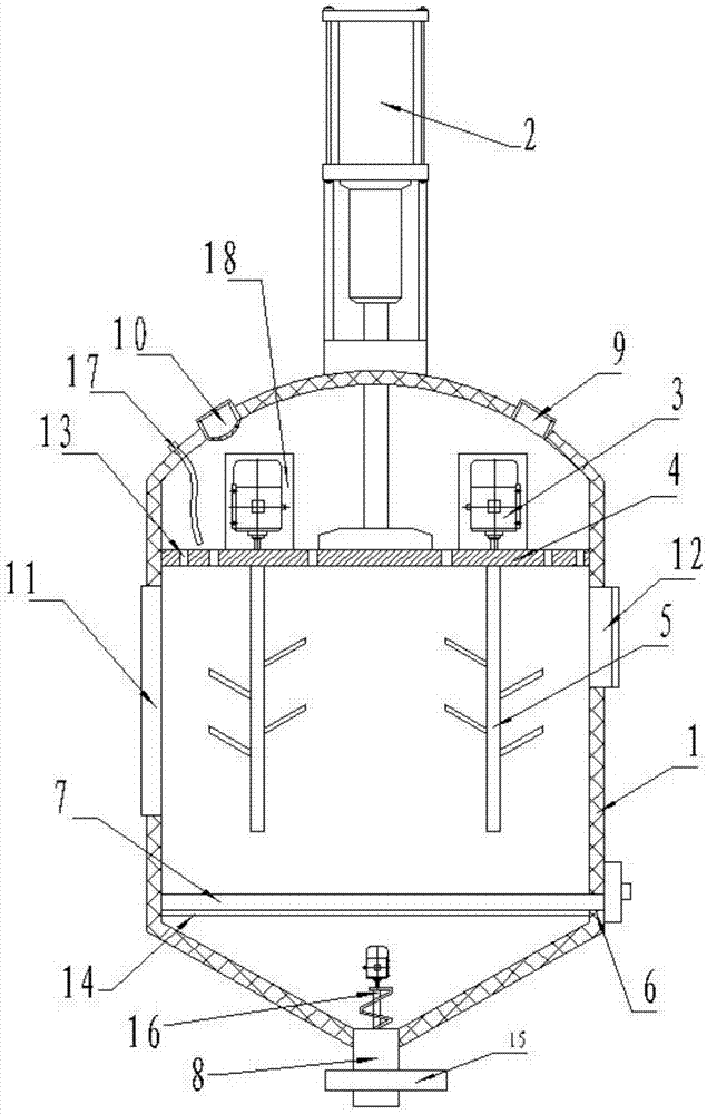
[0015] Such as figure 1 As shown, a biological fermentation tank 1 includes a tank 1, a three-stage telescopic cylinder 2, a frequency conversion motor 3, a cleaning filter press 4 and a stirring rod 5, and the three-stage telescopic cylinder 2 is fixed on the top of the tank 1 , the cleaning filter press plate 4 is horizontally placed on the top of the tank body 1, and the place where the cleaning filter press plate 4 is in contact with the tank body 1 is provided with a sealing strip, and the telescopic end of the three-stage telescopic cylinder 2 extends into the inside of the tank body 1 to connect with the cleaning filter press The plate 4 is fixedly connected to drive the cleaning filter press plate 4 to move up and down; 1-2 variable frequency motors 3 are fixed on the upper end of the cleaning filter press plate 4, and the number of variable frequency motors 3 is set under the cleaning filter press plate 4. Stirring bar 5, and frequency conversion motor 3 rotating shaf...


PUM


Abstract

The invention relates to a biological fermentation tank body. A three-stage telescopic cylinder is fixed on the top of the tank body. A cleaning filter press plate is horizontally placed on the top of the tank body. The telescopic end extends into the inside of the tank and is fixedly connected with the cleaning filter press plate; 1-2 frequency conversion motors are fixed on the upper end of the cleaning filter press plate, and stirring rods with the same number as the frequency conversion motors are arranged under the cleaning filter press plate. And the rotating shaft of the frequency conversion motor is connected with the stirring rod, which is used to drive the stirring rod to stir the fermentation raw materials; there is an opening on one side of the tank body, and a suspension plate that can be pulled out from the opening of the tank body is horizontally arranged at the lower part of the tank body. There is a fermentation material outlet; the top of the tank is provided with an openable air hole and a water spray port; a transparent observation window is provided on the side wall of the tank, and a feed port is arranged on the side wall of the tank for sealing connection. The invention has reasonable structural design and simple operation, and can be popularized and used in the field of biotechnology.

Description

technical field [0001] The invention belongs to the technical field of biological fermentation, and in particular relates to a biological fermentation tank body. Background technique [0002] The biological fermentation device is the most commonly used basic equipment in bioengineering production. Whether the design of the biological fermentation device is reasonable will directly affect the product quality. But the existing products all have some deficiencies in this respect: 1. Most of the existing fermentation devices are provided with only one cleaning hole, and there is a blind spot when cleaning the inside of the tank body, resulting in incomplete cleaning, and it is difficult to adapt to products with higher quality requirements. 2. Most of the existing fermentation devices can only provide the same fermentation temperature environment as the external temperature, and the external temperature is constantly changing, which makes the microorganisms in the fermentation t...

Claims


Application Information

Patent Timeline
Patent Type & Authority Applications(China)
IPC IPC(8): C12M1/38C12M1/36C12M1/02C12M1/00
CPCC12M41/12C12M23/22C12M27/02C12M39/00C12M41/34
Inventor 李秋红
Owner 李秋红
Why Eureka
Try Eureka