
Centrifugal fan supporting structure

A technology for supporting structures and centrifugal fans, applied in mechanical equipment, machines/engines, liquid fuel engines, etc., can solve problems such as increased maintenance costs, inability to be used in general, delays, etc., and achieve the effect of rapid assembly and disassembly

Pending Publication Date: 2017-12-15
FOSHAN CITY NANHAI POPULA FAN
View PDF6 Cites 0 Cited by
  • Summary
  • Abstract
  • Description
  • Claims
  • Application Information

AI Technical Summary

Problems solved by technology

Due to the welding process, for each fan, each support bracket and bushing are compatible and cannot be used universally. Once the support bracket and bushing are damaged, if maintenance is required, the entire fan needs to be sent back Adaptive repairs are made to the manufacturer, which will lead to delays in production for users and increase maintenance costs

Method used

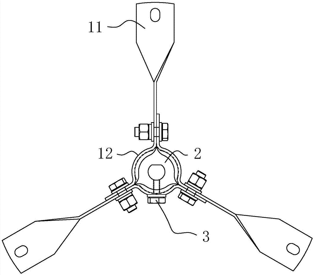
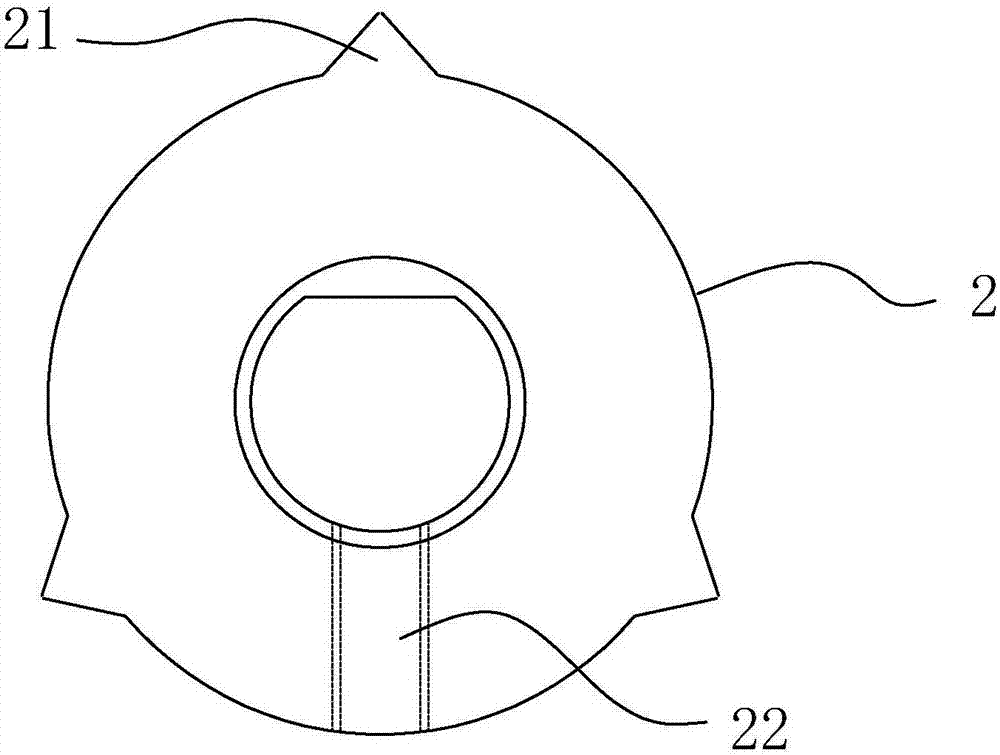
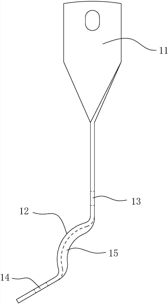

Image

  • Centrifugal fan supporting structure
  • Centrifugal fan supporting structure
  • Centrifugal fan supporting structure

Examples


Embodiment Construction

[0018] The idea, specific structure and technical effects of the present invention will be clearly and completely described below in conjunction with the embodiments and accompanying drawings, so as to fully understand the purpose, features and effects of the present invention. Apparently, the described embodiments are only some of the embodiments of the present invention, rather than all of them. Based on the embodiments of the present invention, other embodiments obtained by those skilled in the art without creative efforts belong to The protection scope of the present invention. In addition, all the connection / connection relationships mentioned in this article do not refer to the direct connection of components, but mean that a better connection structure can be formed by adding or reducing connection accessories according to specific implementation conditions. The various technical features in the present invention can be combined interactively on the premise of not confli...


PUM


Abstract

The invention discloses a centrifugal fan supporting structure. The centrifugal fan supporting structure comprises a plurality of supporting supports and further comprises a shaft sleeve; the front end and the back end of each supporting support are a machine body connecting end and a shaft connecting end correspondingly; the shaft connecting ends of the supporting supports are in abutting joint with the peripheral wall of the shaft sleeve sequentially; the two sides of the front and back of each shaft connecting end are provided with a front through hole and a back through hole correspondingly; the front through hole of each supporting support is connected with the back through hole of the corresponding supporting support beside the supporting support; a sleeve hole in which the shaft sleeve can be arranged in a sleeved manner is defined by the shaft connecting ends of the supporting supports; chamfers are arranged between the shaft connecting ends and the front through holes as well as between the shaft connecting ends and the back through holes, so that the sleeve hole is provided with a plurality of sunken parts; and a plurality of protruding locking parts are annularly arrayed on the peripheral wall of the shaft sleeve. Due to the split type arrangement of the supporting supports and the shaft sleeve, assembling, disassembling, and maintaining can be fast performed. Due to the arrangement of the locking parts, it can be prevented that mutual displacement is generated between the supporting supports and the shaft sleeve. The centrifugal fan supporting structure is used for centrifugal fans.

Description

technical field [0001] The invention relates to a centrifugal fan support structure. Background technique [0002] The support bracket and the shaft sleeve adopt a welded structure, which will cause fracture due to weak welding, difficult to ensure positioning, and uneven appearance. When assembling the fan, the paint on the inner hole of the steel shaft sleeve needs to be cleaned, and the installation is troublesome and difficult to adjust. Due to the welding process, for each fan, each support bracket and bushing are compatible and cannot be used universally. Once the support bracket and bushing are damaged, if maintenance is required, the entire fan needs to be sent back Adaptive repairs are made to the manufacturer, which will lead to delays in production for users and increase maintenance costs. Contents of the invention [0003] The technical problem to be solved by the present invention is to provide a support structure for a centrifugal fan. [0004] The solution...

Claims


Application Information

Patent Timeline
IPC IPC(8): F04D29/62
CPCF04D29/626
Inventor 胡锦康唐秀文
Owner FOSHAN CITY NANHAI POPULA FAN
Learn More