
Combined type rotor unmanned aerial vehicle

An unmanned and combined rotor rotor technology, applied in the field of aircraft, can solve the problems of high maintenance costs, fuselage arm damage, and non-detachable arms of bombers

Inactive Publication Date: 2018-02-09
ANHUI WALTER MACHINERY TRADE
View PDF5 Cites 9 Cited by
  • Summary
  • Abstract
  • Description
  • Claims
  • Application Information

AI Technical Summary

Problems solved by technology

[0002] The rotor UAV includes a fuselage, a landing gear and an arm assembly. The arm assembly has an arm and a propeller. The propeller is located at the end of the arm. The fuselage and the arm are usually made of carbon fiber, and the arm is not detachable. During the process, due to the vibration of the aircraft or touching some objects, it is easy to cause damage to the fuselage arm. Because the arm is not detachable, it is very inconvenient to repair the drone. When taking the aircraft to the place where it needs to be used During the process, due to the large size of the drone, it is easy to damage the drone
Foldable drones have appeared now, basically using carbon fiber fuselage, and the folded parts are made of aviation aluminum. After folding, the volume is small and convenient for transportation, but they are most afraid of bombing. The maintenance cost of bombing is expensive and the maintenance cycle is long.

Method used


Image

  • Combined type rotor unmanned aerial vehicle
  • Combined type rotor unmanned aerial vehicle

Examples


Embodiment Construction

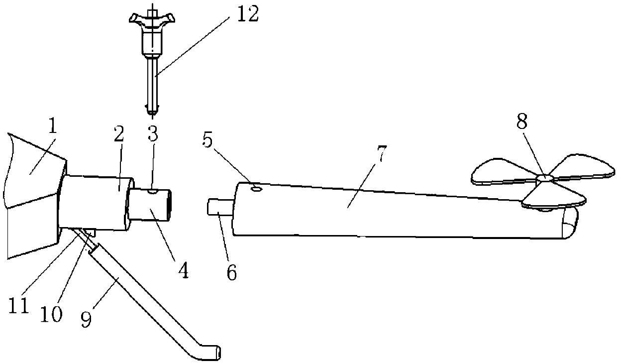
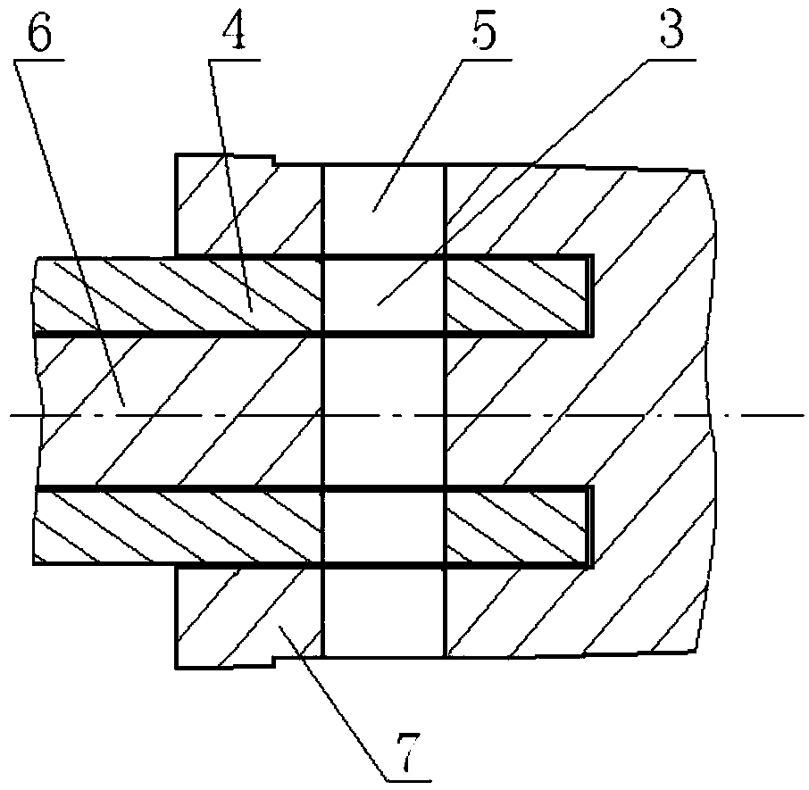
[0012] Such as figure 1 , figure 2 As shown, a combined rotor UAV includes a fuselage 1, a landing gear and an arm assembly. The fuselage 1 has a base 2, and the base 2 is provided with a connecting pipe 12 extending from it. The connecting pipe 12 has a vertical At the first through hole 3 on the center line of the connecting pipe, the arm assembly has an arm 7 and a propeller 8, the propeller 8 is located at the end of the arm 7, and the end of the arm 7 away from the propeller 8 is provided with a protruding connecting column 6 and connected with the propeller 8. The ring groove (not shown) that the connecting pipe 4 is suitable for, the second through hole 5 perpendicular to the center line of the connecting column 6 is arranged on the machine arm 7, and the connecting pipe 4 of the base 2 stretches into the ring of the machine arm 7 during assembly. At the same time, the connecting column 6 of the machine arm 7 extends into the connecting pipe 4 of the machine base 2. T...


PUM


Abstract

The invention discloses a combined type rotor unmanned aerial vehicle comprising a fuselage, an undercarriage and vehicle arm assemblies. The vehicle arm assemblies are provided with vehicle arms andpropellers, wherein the propellers are located at the tail ends of the vehicle arms; a vehicle seat is arranged on the fuselage and provided with extending connecting pipes; the connecting pipes are provided with first through holes perpendicular to the center lines of the connecting pipes; extending connecting columns and annular grooves matched with the connecting pipes are formed in the ends, away from the propellers, of the vehicle arms; the vehicle arms are provided with second through holes perpendicular to the center lines of the connecting columns; and during assembly, the connecting pipes of the vehicle seat extend into the annular grooves of the vehicle arms, meanwhile the connecting columns of the vehicle arms extend into the connecting pipes of the vehicle seat, and inserting of quick-detaching positioning pins can be guaranteed through the positions of the first through holes in the connecting pipes and the positions of the second through holes in the vehicle arms. According to the combined type rotor unmanned aerial vehicle adopting the structure, the vehicle arm assemblies can be detached and carried conveniently, the damaged vehicle arm assemblies can be replaced conveniently, transport is facilitated, damaged pieces can be replaced rapidly, the maintenance cost for the damaged unmanned aerial vehicle falling abnormally is reduced, and the using cost of a user is reduced.

Description

technical field [0001] The invention relates to the field of aircraft, in particular to a combined rotor unmanned aerial vehicle. Background technique [0002] The rotor UAV includes a fuselage, a landing gear and an arm assembly. The arm assembly has an arm and a propeller. The propeller is located at the end of the arm. The fuselage and the arm are usually made of carbon fiber, and the arm is not detachable. During the process, due to the vibration of the aircraft or touching some objects, it is easy to cause damage to the fuselage arm. Because the arm is not detachable, it is very inconvenient to repair the drone. When taking the aircraft to the place where it needs to be used During the process, due to the large size of the drone, it is easy to damage the drone. Foldable drones have appeared now, basically using carbon fiber fuselage, and the folded parts are made of aviation aluminum. After folding, the volume is small and convenient for transportation, but they are mo...

Claims


Application Information

Patent Timeline
IPC IPC(8): B64C27/08B64C1/00
CPCB64C1/069B64C27/08B64U10/10
Inventor 唐小华
Owner ANHUI WALTER MACHINERY TRADE
Learn More