
Array substrate, display panel and display device

An array substrate and substrate substrate technology, which is applied in optics, instruments, electrical digital data processing, etc., can solve the problems that the circuit cannot be set flush, and it is difficult to compress the space and narrow frame.

Active Publication Date: 2017-12-15
XIAMEN TIANMA MICRO ELECTRONICS
View PDF11 Cites 34 Cited by
  • Summary
  • Abstract
  • Description
  • Claims
  • Application Information

AI Technical Summary

Problems solved by technology

Due to the problem of pixel misalignment in the frame area of ​​the special-shaped display screen, the above-mentioned circuits cannot be arranged flush at the frame position, which makes the left and right sides of the upper frame need to be increased by 50 μm, so it is difficult to compress the space in the existing technology to achieve a narrow frame

Method used


Image

  • Array substrate, display panel and display device
  • Array substrate, display panel and display device
  • Array substrate, display panel and display device

Examples


Embodiment Construction

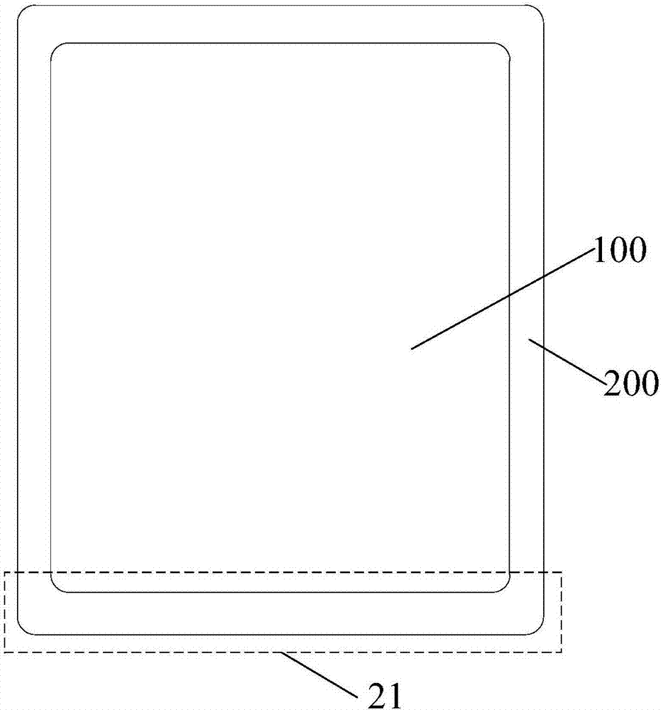
[0045] Embodiments of the present invention provide an array substrate, a display panel, and a display device, which are used to simplify line distribution in non-display areas and compress space to achieve narrow frame design.

[0046]In order to make the above objects, features and advantages of the present invention more comprehensible, the present invention will be further described below in conjunction with the accompanying drawings and embodiments. Example embodiments may, however, be embodied in many forms and should not be construed as limited to the embodiments set forth herein; rather, these embodiments are provided so that this disclosure will be thorough and complete, and will fully convey the concept of example embodiments to those skilled in the art. The same reference numerals denote the same or similar structures in the drawings, and thus their repeated descriptions will be omitted. The words expressing position and direction described in the present invention...


PUM


Abstract

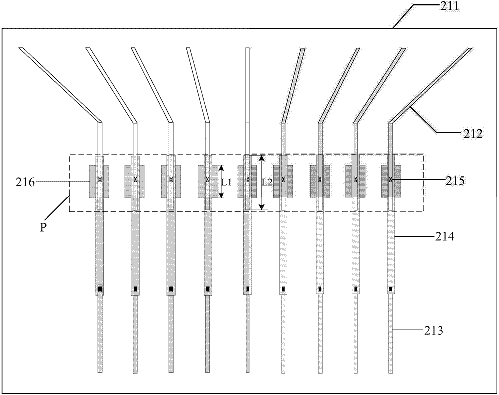
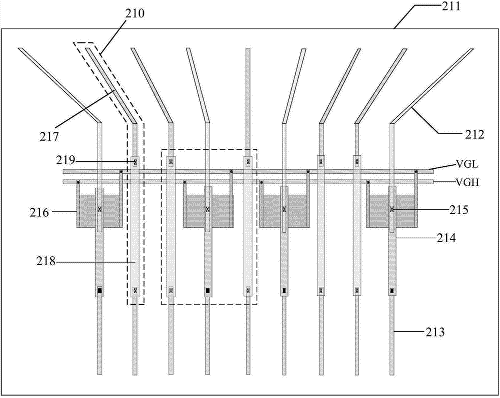
The invention discloses an array substrate, a display panel and a display device. A first non-display area includes an underlayer substrate, multiple touch fan outlet lines arranged on the underlayer substrate, a first binding pin, and multiple touch connecting lines arranged between the touch fan outlet lines and the first binding pin to connect; the touch fan outlet lines and the touch connecting lines are arranged on different film layers, and connected in an one-to-one correspondence mode through passing holes; the orthographic projections, in the underlayer substrate, of the touch fan outlet lines and the correspondingly connected touch connecting lines have an overlapped area; each touch electrostatic-protection circuit is correspondingly connected with each touch connecting line, and the orthographic projections , in the underlayer substrate, of the touch electrostatic-protection circuits are partially overlapped with the overlapped area. The touch electrostatic-protection circuits are arranged in the overlapped area of the touch fan outlet lines and the touch connecting lines, and therefore do not take up other wiring space additionally, so that space originally required by the touch electrostatic-protection circuits to take up is saved so as to shorten a border where the non-display area is positioned to realize the narrow border.

Description

technical field [0001] The invention relates to the field of display technology, in particular to an array substrate, a display panel and a display device. Background technique [0002] With the rapid development of display technology, in addition to the traditional information display and other functions of the display, the requirements for appearance are also gradually increasing. Large screen-to-body ratio is the future development trend of the market. In order to meet the needs of users for the appearance of the display, special-shaped designs can be made on the display screen, such as C / R cut, that is, the display screen is chamfered in a straight line or curved. The special-shaped design can make the display screen have better mechanical strength, It can also enhance the reliability of the display screen and obtain a better appearance effect. [0003] Generally, switch circuits, data signal lines, and protection circuits for touch signal lines are usually arranged on...

Claims


Application Information

Patent Timeline
IPC IPC(8): G02F1/1362G02F1/1333G06F3/041
CPCG02F1/13338G02F1/136204G02F1/136286G02F2202/22G06F3/0412
Inventor 李元行陈国照李作银
Owner XIAMEN TIANMA MICRO ELECTRONICS
Learn More