Full-inorganic perovskite solar energy cell and preparation method thereof

A solar cell and inorganic calcium technology, applied in circuits, electrical components, photovoltaic power generation, etc., can solve problems such as poor contact and charge obstruction, and achieve the effects of reducing requirements, reducing charge recombination, and increasing contact area

Inactive Publication Date: 2017-07-18
HUAZHONG UNIV OF SCI & TECH
View PDF2 Cites 12 Cited by
  • Summary
  • Abstract
  • Description
  • Claims
  • Application Information

AI Technical Summary

Problems solved by technology

However, due to the poor contact between the migration of Cd ions and the interface, there is a large charge hindrance between the planar CdS and the perovskite layer.

Method used


Image

  • Full-inorganic perovskite solar energy cell and preparation method thereof
  • Full-inorganic perovskite solar energy cell and preparation method thereof
  • Full-inorganic perovskite solar energy cell and preparation method thereof

Examples


Embodiment 1

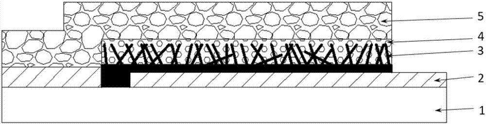
[0034] Referring to the accompanying drawings, an all-inorganic perovskite solar cell comprises a substrate glass 1, an ITO conductive layer 2 and a photoanode 3, a light absorbing layer 4 and a carbon counter electrode layer 5, wherein,

[0035]The ITO conductive layer 2 is arranged on the upper surface of the substrate glass 1;

[0036] The photoanode 3 is a CdS nanorod array structure, which is arranged on the upper surface of the ITO conductive layer 2 and has a pore structure;

[0037] The light absorbing layer 4 is CsPbBr 3 an inorganic perovskite layer embedded within the pore structure of the photoanode 3 to form intimate contact with the photoanode 3;

[0038] The carbon counter electrode layer 5 is spread on the upper surface of the ITO conductive layer 2 and the upper surface of the light absorbing layer 4 , which is formed by screen printing.

[0039] Further, the CdS nanorods of the CdS nanorod array are prepared by a hydrothermal method, and each of the CdS nan...

Embodiment 2

[0048] Referring to the accompanying drawings, an all-inorganic perovskite solar cell comprises a substrate glass 1, an ITO conductive layer 2 and a photoanode 3, a light absorbing layer 4 and a carbon counter electrode layer 5, wherein,

[0049] The ITO conductive layer 2 is arranged on the upper surface of the substrate glass 1;

[0050] The photoanode 3 is a CdS nanorod array structure, which is arranged on the upper surface of the ITO conductive layer 2 and has a pore structure;

[0051] The light absorbing layer 4 is CsPbBr 3 an inorganic perovskite layer embedded within the pore structure of the photoanode 3 to form intimate contact with the photoanode 3;

[0052] The carbon counter electrode layer 5 is spread on the upper surface of the ITO conductive layer 2 and the upper surface of the light absorbing layer 4 , which is formed by screen printing.

[0053] Further, the CdS nanorods of the CdS nanorod array are prepared by a hydrothermal method. The diameter of each C...

Embodiment 3

[0062] Referring to the accompanying drawings, an all-inorganic perovskite solar cell comprises a substrate glass 1, an ITO conductive layer 2 and a photoanode 3, a light absorbing layer 4 and a carbon counter electrode layer 5, wherein,

[0063] The ITO conductive layer 2 is arranged on the upper surface of the substrate glass 1;

[0064] The photoanode 3 is a CdS nanorod array structure, which is arranged on the upper surface of the ITO conductive layer 2 and has a pore structure;

[0065] The light absorbing layer 4 is CsPbBr 3 an inorganic perovskite layer embedded within the pore structure of the photoanode 3 to form intimate contact with the photoanode 3;

[0066] The carbon counter electrode layer 5 is spread on the upper surface of the ITO conductive layer 2 and the upper surface of the light absorbing layer 4 , which is formed by screen printing.

[0067] Further, the CdS nanorods of the CdS nanorod array are prepared by a hydrothermal method, each of the CdS nanoro...


PUM

PropertyMeasurementUnit
diameteraaaaaaaaaa
lengthaaaaaaaaaa
thicknessaaaaaaaaaa

Abstract

The invention belongs to the micro nano manufacture technical field, and discloses a full-inorganic perovskite solar energy cell comprising a substrate glass, an ITO conductive layer and a photoanode, a luminous absorption layer and a carbon counter electrode layer; the photoanode is a CdS nanorod array structure having aperture structures; the luminous absorption layer is a CsPbBr3 inorganic perovskite layer embedded in the aperture structures of the photoanode, thus tightly contacting with the photoanode; the carbon counter electrode layer is paved on the top surface of the ITO conductive layer and the top surface of the luminous absorption layer, and formed by screen printing films. The contact areas between the perovskite layer and an electron transmission layer can be obviously improved, thus increasing the charge transmission channels; UV ozone processing is carried out for the grown CdS nanorod array, thus obviously improving the CdS film interface characteristics, reducing crystal grain boundaries, reducing electron defect density of states, reducing unfavorable charge recombination, and improving the electron transmission characteristics.

Description

technical field [0001] The invention belongs to the technical field of micro-nano manufacturing, and more specifically relates to a perovskite solar cell and a preparation method thereof. Background technique [0002] In the field of energy, with the development of industry, the fossil energy contained in the earth is gradually being exhausted, and solar energy, as an inexhaustible clean energy, has become the focus of human development, while traditional inorganic solar cells are due to the preparation process The disadvantages such as complexity, strict production environment requirements, and large environmental pollution no longer meet the requirements of the further development of human society. Therefore, new solar cells such as perovskite solar cells are becoming a research hotspot. Since 2009, Japan's Miyasaka et al. first used organometallic halide CH with a perovskite structure 3 NH 3 PbBr 3 and CH 3 NH 3 PB 3 Since the research on perovskite solar cells was ...

Claims


Application Information

Patent Timeline
Patent Type & Authority Applications(China)
IPC IPC(8): H01L31/0224H01L31/032H01L31/18
CPCH01L31/022425H01L31/032H01L31/18Y02E10/50Y02P70/50
Inventor 廖广兰刘星月史铁林刘智勇韩京辉涂玉雪叶海波汤自荣
Owner HUAZHONG UNIV OF SCI & TECH
Why Eureka
Try Eureka