Integrated circuit board dedusting device for integrated circuit testing

A technology for integrated circuit boards and integrated circuits, applied in cleaning methods and appliances, cleaning methods using tools, cleaning methods using gas flow, etc., can solve problems such as high labor intensity, insufficient dust removal, and time-consuming and laborious manual dust removal.

Inactive Publication Date: 2017-12-19
郑世珍
View PDF8 Cites 11 Cited by
  • Summary
  • Abstract
  • Description
  • Claims
  • Application Information

AI Technical Summary

Problems solved by technology

[0005] In order to overcome the shortcomings of time-consuming and labor-intensive manual dust removal, high labor intensity, and insufficient dust removal, the technical problem to be solved by the present invention is to provide an integrated circuit board dust removal device for integrated circuit testing that saves time and labor, has low labor intensity, and is sufficiently thorough for dust removal. equipment

Method used


Image

  • Integrated circuit board dedusting device for integrated circuit testing
  • Integrated circuit board dedusting device for integrated circuit testing
  • Integrated circuit board dedusting device for integrated circuit testing

Examples


Embodiment 1

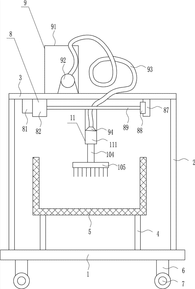
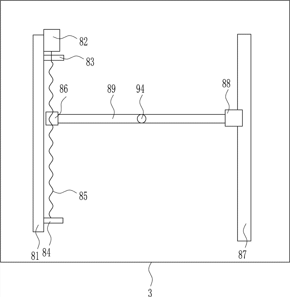
[0038] An integrated circuit board dust removal device for integrated circuit testing, such as Figure 1-8 As shown, it includes a base plate 1, a bracket 2, a top plate 3, a pole 4, a mesh box 5, a riser 6, wheels 7, a front and rear moving device 8 and an air blowing device 9, and the top of the base plate 1 is symmetrically connected by bolts. Brackets 2 are installed in the same way, the top of the two brackets 2 is connected by bolts to install the top plate 3, the top of the bottom plate 1 is symmetrically installed with the support rod 4 by the bolt connection, and the top of the support rod 4 is connected by the bolt. The box 5 and the support rod 4 are located between the two brackets 2. The bottom of the bottom plate 1 is symmetrically installed with a vertical plate 6 connected by bolts. The bottom of the two vertical plates 6 is equipped with wheels 7, and the bottom of the top plate 3 is equipped with a front and rear moving device 8. , top plate 3 top left side i...

Embodiment 2

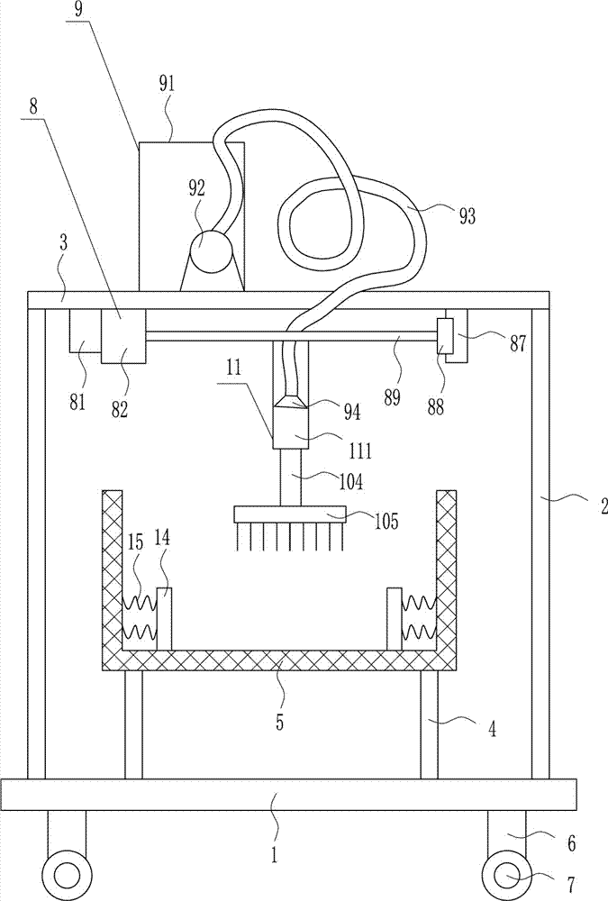
[0040] An integrated circuit board dust removal device for integrated circuit testing, such as Figure 1-8 As shown, it includes a base plate 1, a bracket 2, a top plate 3, a pole 4, a mesh box 5, a riser 6, wheels 7, a front and rear moving device 8 and an air blowing device 9, and the top of the base plate 1 is symmetrically connected by bolts. Brackets 2 are installed in the same way, the top of the two brackets 2 is connected by bolts to install the top plate 3, the top of the bottom plate 1 is symmetrically installed with the support rod 4 by the bolt connection, and the top of the support rod 4 is connected by the bolt. The box 5 and the support rod 4 are located between the two brackets 2. The bottom of the bottom plate 1 is symmetrically installed with a vertical plate 6 connected by bolts. The bottom of the two vertical plates 6 is equipped with wheels 7, and the bottom of the top plate 3 is equipped with a front and rear moving device 8. , top plate 3 top left side i...

Embodiment 3

[0043] An integrated circuit board dust removal device for integrated circuit testing, such as Figure 1-8 As shown, it includes a base plate 1, a bracket 2, a top plate 3, a pole 4, a mesh box 5, a riser 6, wheels 7, a front and rear moving device 8 and an air blowing device 9, and the top of the base plate 1 is symmetrically connected by bolts. Brackets 2 are installed in the same way, the top of the two brackets 2 is connected by bolts to install the top plate 3, the top of the bottom plate 1 is symmetrically installed with the support rod 4 by the bolt connection, and the top of the support rod 4 is connected by the bolt. The box 5 and the support rod 4 are located between the two brackets 2. The bottom of the bottom plate 1 is symmetrically installed with a vertical plate 6 connected by bolts. The bottom of the two vertical plates 6 is equipped with wheels 7, and the bottom of the top plate 3 is equipped with a front and rear moving device 8. , top plate 3 top left side i...


PUM


Abstract

The invention relates to integrated circuit board dedusting devices, in particular to an integrated circuit board dedusting device for integrated circuit testing. According to the integrated circuit board dedusting device for integrated circuit testing, the time and labor are saved, the labor intensity is small, and dedusting is enough thorough. The integrated circuit board dedusting device for integrated circuit testing comprises a bottom plate, brackets, a top plate and the like; the brackets are mounted at the top of the bottom plate in bilateral symmetry and bolt connection modes; the top plate is mounted at the tops of the two brackets in a bolt connection mode; and supporting rods are at the top of the bottom plate in bilateral symmetry and bolt connection modes. A front-rear moving device drives an air blowing part of an air blowing device to move in the front-rear direction, so that the circuit board cleaning effect is better; and a dust wiping device is arranged, the circuit board cleaning effect is further improved, and the effects that the time and labor are saved, the labor intensity is small, and dedusting is enough thorough are achieved.

Description

technical field [0001] The invention relates to an integrated circuit board dust removal device, in particular to an integrated circuit board dust removal device for integrated circuit testing. Background technique [0002] An integrated circuit is a tiny electronic device or component. Using a certain process, the transistors, resistors, capacitors, inductors and other components required in a circuit are interconnected, and they are fabricated on a small or several small semiconductor wafers or dielectric substrates, and then packaged in a tube. , and become a microstructure with required circuit functions; all the components in it have been structurally integrated, making electronic components a big step towards miniaturization, low power consumption, intelligence and high reliability. It is represented by the letter "IC" in the circuit. The inventors of the integrated circuit are Jack Kilby (germanium (Ge)-based integrated circuits) and Robert Noyce (silicon (Si)-based...

Claims


Application Information

Patent Timeline
Patent Type & Authority Applications(China)
IPC IPC(8): B08B5/02B08B1/00
CPCB08B5/02B08B1/002B08B1/008
Inventor 周晓东张健刘超群阳冬
Owner 郑世珍
Why Eureka
Try Eureka