Eureka AIR delivers breakthrough ideas for toughest innovation challenges, trusted by R&D personnel around the world.

Heat shrinkage film take-up device

A technology of winding device and heat-shrinkable film, which is applied in the field of thermoplastic film processing, can solve problems such as the inability to complete automatic unloading, achieve the effects of reducing labor intensity, improving winding effect, and reducing costs

Active Publication Date: 2017-12-19
贵州亿博科技有限公司
View PDF7 Cites 4 Cited by
  • Summary
  • Abstract
  • Description
  • Claims
  • Application Information

AI Technical Summary

Problems solved by technology

[0005] The present invention intends to provide a heat-shrinkable film winding device to solve the problem that automatic unloading cannot be completed in the prior art

Method used


Image

  • Heat shrinkage film take-up device
  • Heat shrinkage film take-up device
  • Heat shrinkage film take-up device

Examples

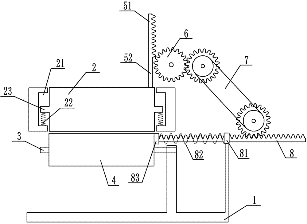
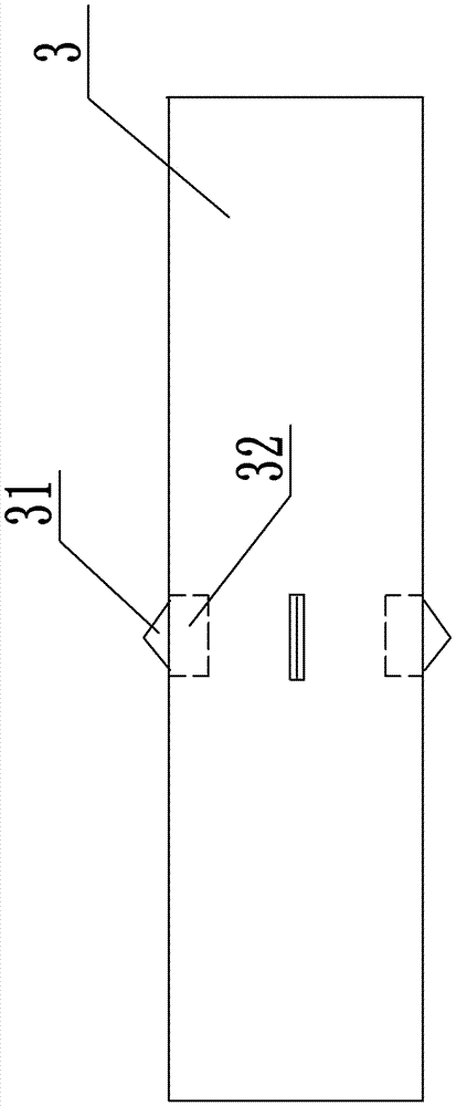
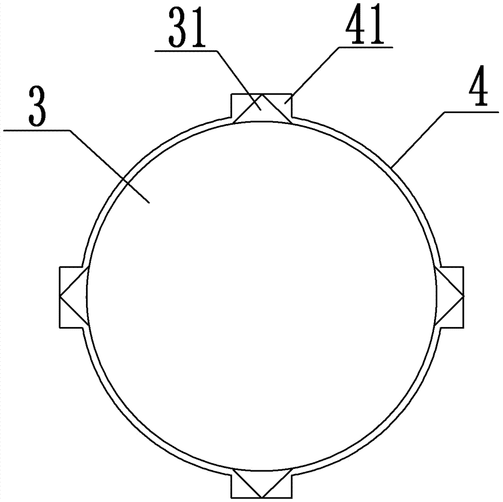

Embodiment Construction

[0026] The present invention will be described in further detail below by means of specific embodiments:

[0027] The reference signs in the accompanying drawings of the specification include: frame 1, pressure roller 2, guide groove 21, second elastic member 22, pressure roller shaft 23, winding shaft 3, retractable block 31, block groove 32, film roll 4. Groove 41 , toothed part 51 , non-toothed part 52 , driving gear 6 , transmission mechanism 7 , first rack 8 , limit ring 81 , first elastic member 82 , and push block 83 .

[0028] The embodiment is basically as figure 1 , figure 2 , image 3 Shown:

[0029] The heat-shrinkable film winding device provided in this embodiment includes:

[0030] Frame 1, the frame 1 is provided with a winding shaft 3, one end of the winding shaft 3 is rotationally connected with the frame 1 through a bearing, the other end of the winding shaft 3 is a cantilever end, and the winding shaft 3 is equipped with an axial freedom The film roll...


PUM


Abstract

The invention discloses a heat shrinkage film take-up device. The heat shrinkage film take-up device comprises a frame, driving gears and a first rack, wherein a take-up shaft is arranged on the frame; one end of the take-up shaft is rotationally connected with the frame, and the other end of the take-up shaft is a cantilevered end; a film roll with axial freedom sleeves the take-up shaft; a compression roller with vertical freedom only is arranged above the take-up shaft; a vertically upward second rack is arranged at the upper end of the compression roller; the second rack comprises a toothed part and a non-toothed part positioned at the lower end of the toothed part; the driving gears mesh with the toothed part; the first rack is horizontally arranged on the side surface of the take-up shaft; a transmission mechanism capable for converting circular motion of the driving gears into horizontal motion of the second rack is arranged on the frame; a limiting buckle allowing the first rack to penetrate is arranged on the frame; a first elastic piece is arranged between the limiting buckle and the end, close to the side of the take-up shaft, of the first rack; and the first rack can be driven by the first elastic piece to push the film roll out of the take-up shaft. By adoption of the scheme, the problem that automatic unrolling cannot be finished in the prior art can be effectively solved.

Description

technical field [0001] The invention belongs to the technical field of thermoplastic film processing, and in particular relates to a heat-shrinkable film winding device. Background technique [0002] In the film production line, the auxiliary equipment that winds the produced film on the paper core to form a roll is called a winder or a coiler. [0003] During the winding process of the film, the cooperation of the pressure roller and the winding roller is usually required to timely discharge the air in the film roll and flatten the film surface so as to achieve the purpose of dense film roll and smooth film surface. At present, the commonly used winding devices for heat shrinkable films are generally used in conjunction with a pressure roller and a winding roller up and down. By applying a certain pressure on the pressure roller, the pressure roller is closely attached to the winding roller to achieve The purpose of exhaust flattening. Considering the effect of friction a...

Claims


Application Information

Patent Timeline
IPC IPC(8): B65H18/02B65H18/10B65H19/30B65H18/26B65H23/34
CPCB65H18/026B65H18/10B65H18/26B65H19/30B65H23/34B65H2301/418B65H2701/1133B65H2701/1752
Inventor 李云学
Owner 贵州亿博科技有限公司
Why Eureka
Eureka Blog
Learn More