Lead drawing device for embroidering machine

An embroidery machine and lead thread technology, which is applied to the mechanism of embroidery machines, embroidery machines, textiles and papermaking, etc., can solve the problems of large lead angle, inability to adjust, broken thread, etc., to reduce the lead angle, avoid excessive friction, good versatility

Inactive Publication Date: 2017-12-19
陈钦楠
View PDF0 Cites 0 Cited by
  • Summary
  • Abstract
  • Description
  • Claims
  • Application Information

AI Technical Summary

Problems solved by technology

However, due to the high friction between the thread and the iron bar during the guiding process, the thread is easy to wear and tear for a long time, and the thread becomes thinner or even broken, which affects the normal operation of the embroidery machine and also affects the embroidery. quality
In addition, the height difference between the wire lead device and the wire barrel will also affect the wire. If the height difference is too large, the angle of the lead wire is large, and the wire is easily torn off. However, the height of the existing wire lead device is fixed and cannot be adjusted according to needs.

Method used


Image

  • Lead drawing device for embroidering machine
  • Lead drawing device for embroidering machine

Examples


Embodiment Construction

[0015] The following will clearly and completely describe the technical solutions in the embodiments of the present invention with reference to the accompanying drawings in the embodiments of the present invention. Obviously, the described embodiments are only some, not all, embodiments of the present invention.

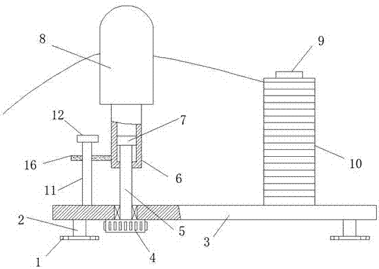
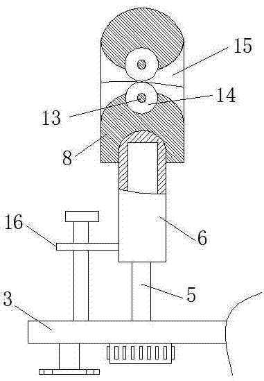
[0016] refer to Figure 1-2 , a lead wire device used on an embroidery machine, including a fixed block 1 fixed on the embroidery machine, a pole 2 is fixed on the top of the fixed block 1, and a mounting plate 3 is fixed on the end of the pole 2 away from the fixed block 1, and the mounting plate The top of 3 is fixed with a plurality of lead wire units along the length direction, and the lead wire unit includes the wire barrel fixing column 9 and the guide rod 11 fixed on the top of the mounting plate 3, the guide rod 11 is located on one side of the wire drum fixing column 9, and the guide rod 11 A limit block 12 is fixed at one end far away from the mounting plat...


PUM


Abstract

The invention discloses a lead wire device for an embroidery machine, which comprises a fixing block fixed on the embroidery machine, a pole is fixed on the top of the fixing block, and a mounting plate is fixed on the end of the pole far away from the fixing block. The top of the board is fixed with a plurality of lead wire units along the length direction, and the lead wire unit includes a wire barrel fixing column and a guide rod fixed on the top of the installation board, and the guide rod is located on one side of the wire drum fixing rod, and the guide rod is far away from the installation board A limit block is fixed at one end of the mounting plate, and a knob is provided under the bottom of the mounting plate. The present invention can adjust the height of the lead block and the lead hole through the cooperative use of wire barrels, fixing columns, knobs, connecting rods, internal thread sleeves and external thread blocks, and can then match with wire barrels of different lengths. The lead hole is adjusted to a proper position to achieve the purpose of reducing the lead angle, so as to avoid the situation that the embroidery thread is broken due to the excessive lead angle.

Description

technical field [0001] The invention relates to the technical field of thread-leading devices, in particular to a thread-leading device used on an embroidery machine. Background technique [0002] When the embroidery machine is working, it is necessary to lead the thread in the thread barrel to the embroidery machine head. At present, a horizontally arranged iron bar is usually used as a lead device to guide the thread in the thread barrel to the embroidery machine head. However, due to the high friction between the thread and the iron bar during the guiding process, the thread is easy to wear and tear over time, and the thread becomes thinner or even broken, which affects the normal operation of the embroidery machine and also affects the embroidery. quality. In addition, the height difference between the lead wire device and the wire barrel will also affect the wire. If the height difference is too large, the lead wire angle is large, and the wire is easily torn off. How...

Claims


Application Information

Patent Timeline
Patent Type & Authority Applications(China)
IPC IPC(8): D05C11/00
CPCD05C11/00
Inventor 陈钦楠
Owner 陈钦楠
Why Eureka
Try Eureka