Motor power unit

A power plant, hydraulic power technology, applied in the direction of machines/engines, mechanical equipment, rotary piston machines, etc., can solve the problems of pollution waste, limited drainage capacity of drainage holes, etc., and achieve the effect of improving drainage capacity.

Active Publication Date: 2019-03-01
JIAXING NEWSTAR MOTOR CO LTD
View PDF6 Cites 0 Cited by
  • Summary
  • Abstract
  • Description
  • Claims
  • Application Information

AI Technical Summary

Problems solved by technology

[0005] The purpose of the present invention is to provide a motor power device to solve the problems in the prior art that the drainage capacity of the drainage hole is limited due to gravity alone, and the direct discharge of the liquid will cause pollution and waste

Method used


Image

  • Motor power unit
  • Motor power unit
  • Motor power unit

Examples


Embodiment Construction

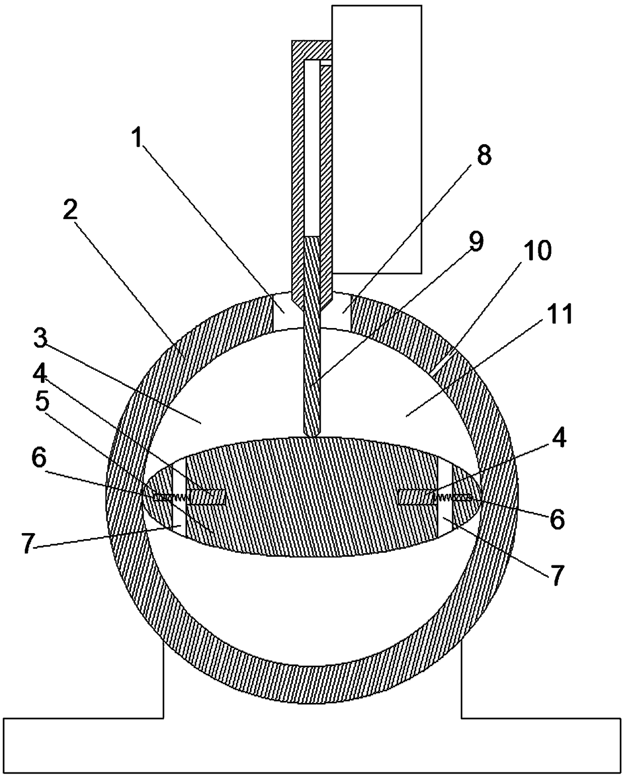
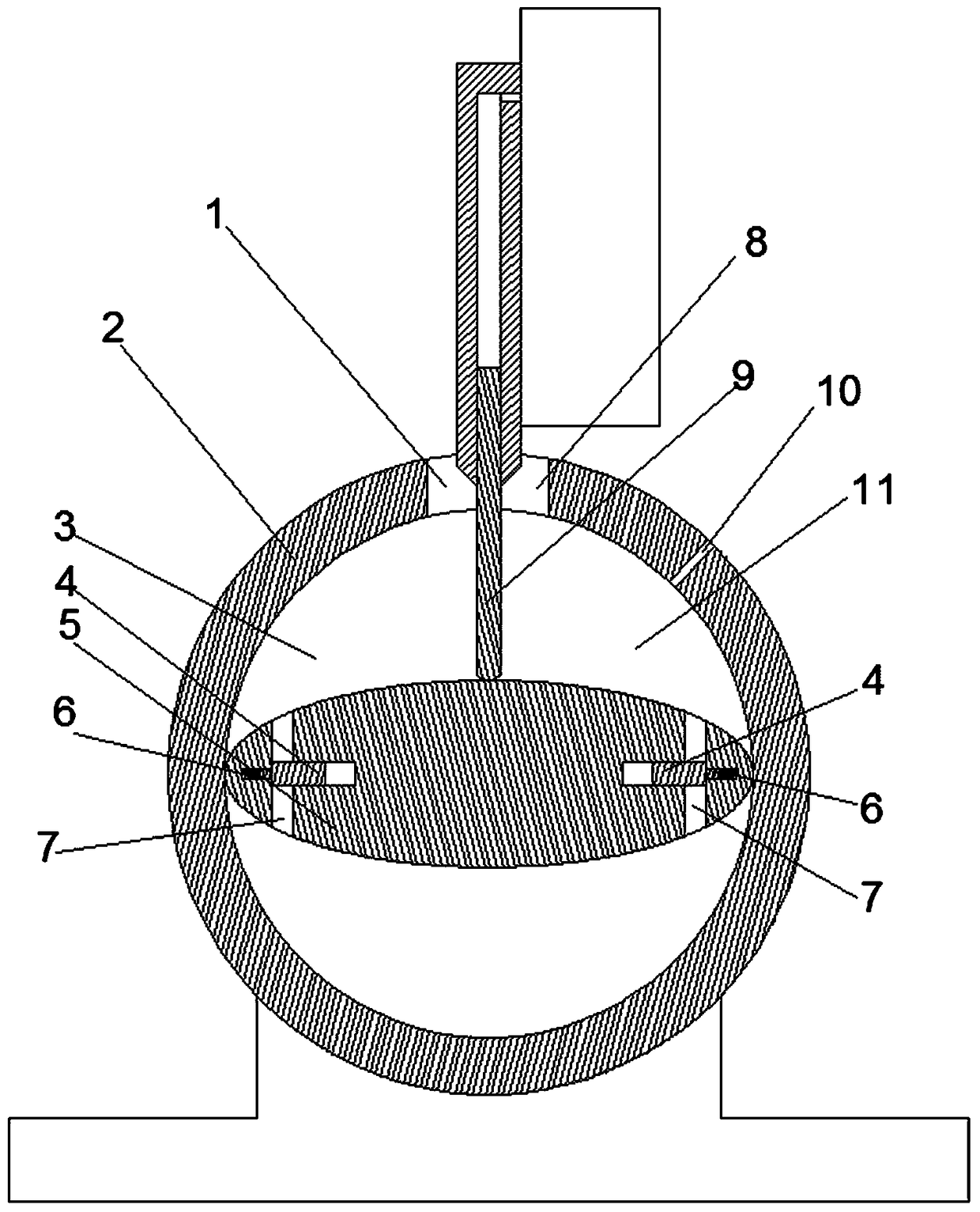
[0019] Examples of motor power units are Figure 1~7 As shown: it includes a motor 37 and a pump 36, the pump 36 includes a pump body 2 with a cylindrical hole inner cavity, the pump body 2 is provided with a pump rotor 5 whose rotation axis extends along the front-to-back direction and has an elliptical cross-section, the pump rotor The cross section of 5 has two tangent points with the cylindrical inner hole. There is a hole on the pump body, and the guiding movement assembly at the hole has one end that slides and pushes with the outer peripheral surface of the pump rotor to separate the hole into a liquid inlet 8, The separator 9 of the liquid outlet 1, the inner cavity of the cylindrical hole is also divided by the separator 9 into a low-pressure chamber 11 connected with the liquid inlet 8 and a high-pressure chamber 3 connected with the liquid outlet 1, and the long diameter direction of the pump rotor is two The end is provided with an oil guide channel 7 connecting bo...


PUM


Abstract

The invention relates to a motor power device. The cross section of a pump rotor and a pump body have at least two points of tangency. The pump body is provided with a liquid inlet and a liquid outlet. The liquid inlet and the liquid outlet are separated through a separation plate assembled on the pump body in a guide mode. One end of the separation plate is in push fit with the peripheral surface of the pump rotor. An inner cavity of a pump comprises a lower pressure cavity communicating with the liquid inlet, and a high pressure cavity communicating with the liquid outlet. The lower pressure cavity communicates with a liquid discharge hole, and the communicating path is provided with a fluid check valve and a switch valve. A device shell is provided with an air inlet in the front side of a dynamic seal mechanism. The air inlet is connected with an air inlet check valve. Through the motor power device, the problems that in the prior art, only gravity is utilized, thus the liquid discharge ability of a liquid discharge hole is limited, and meanwhile, pollution and waste are caused by direct liquid discharge are solved.

Description

technical field [0001] The invention relates to an electric motor power device capable of providing hydraulic power. Background technique [0002] Hydraulic power is more and more widely used in mechanical equipment. The motor power device that can provide hydraulic power includes a motor and a pump. The motor drives the pump to realize oil pumping. Because there is liquid in the pump, and the inside of the motor cannot enter the liquid, the anti-seepage structure between the motor and the pump has a great influence on the service life of the motor. Chinese patent CN102868248A discloses a "anti-seepage structure of pump rotating bearing". The motor includes a motor casing, the pump includes a pump body, the motor casing and the pump body are arranged in front and back, and a dynamic sealing mechanism is arranged between the rotating shaft and the pump body A drain nut is arranged on the front side of the dynamic sealing mechanism on the rotating shaft, an annular groove is ...

Claims


Application Information

Patent Timeline
Patent Type & Authority Patents(China)
IPC IPC(8): F04C11/00F04C2/356F04C15/00F04C15/06
CPCF04C2/3566F04C11/008F04C15/00F04C15/066F04C2240/10F04C2240/20
Inventor 马来勋
Owner JIAXING NEWSTAR MOTOR CO LTD
Why Eureka
Try Eureka