
Equipment fault monitoring system

A technology for monitoring system and equipment failures, which is applied to measuring devices, testing of machine/structural components, instruments, etc. It can solve problems such as limited processing and computing capabilities, inability to meet real-time monitoring and diagnosis, and achieve the effect of satisfying real-time monitoring.

Inactive Publication Date: 2017-12-19
许斌
View PDF0 Cites 4 Cited by
  • Summary
  • Abstract
  • Description
  • Claims
  • Application Information

AI Technical Summary

Problems solved by technology

However, although the traditional handheld data acquisition instrument is small in size, its processing and computing power is limited, which cannot meet the needs of real-time monitoring and diagnosis.

Method used


Image

  • Equipment fault monitoring system

Examples


Embodiment Construction

[0009] In order to facilitate the understanding of the present invention, the present invention will be described more fully below with reference to the associated drawings. Preferred embodiments of the invention are shown in the accompanying drawings. However, the present invention can be embodied in many different forms and is not limited to the embodiments described herein. On the contrary, the purpose of providing these embodiments is to make the disclosure of the present invention more thorough and comprehensive. It should be noted that when an element is considered to be "connected" to another element, it may be directly connected to the other element or there may be intervening elements at the same time. Unless otherwise defined, all technical and scientific terms used herein have the same meaning as commonly understood by one of ordinary skill in the technical field of the invention. The terms used herein in the description of the present invention are for the purpos...


PUM


Abstract

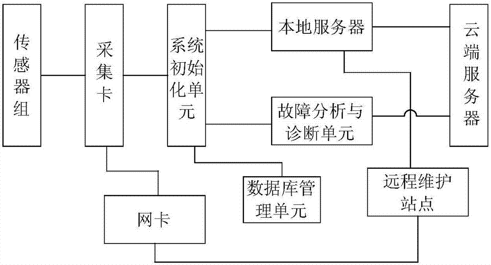
The invention discloses a device fault monitoring system, which includes a sensor group, an acquisition card, a network card, a system initialization unit, a remote monitoring site, a database management unit, a local server, a cloud server, a fault analysis and diagnosis unit, and several handheld terminals; the sensor One end of the group is connected to the monitored equipment, and the other end is connected to the acquisition card; one end of the network card is connected to the acquisition card, and the other end is connected to the remote monitoring site; one end of the system initialization unit is connected to the acquisition card, and the other end is connected to the database management unit; one end of the local server is connected to the The system initialization unit is connected to a cloud server at one end; the fault analysis and diagnosis unit is connected to a local server; and the plurality of handheld terminals are connected to the cloud server through a wireless network.

Description

technical field [0001] The invention relates to the field of equipment failure monitoring, in particular to an equipment failure monitoring system. Background technique [0002] In order to ensure the safe and reliable operation of mechanical equipment, especially large-scale mechanical equipment, state data such as current and voltage of mechanical equipment are generally monitored. However, although the traditional handheld data acquisition instrument is small in size, its processing and computing power is limited, which cannot meet the needs of real-time monitoring and diagnosis. Contents of the invention [0003] The purpose of the present invention is to solve the problems mentioned in the background technology section above through a device fault monitoring system. [0004] For reaching this purpose, the present invention adopts following technical scheme: [0005] A device fault monitoring system, which includes a sensor group, an acquisition card, a network card,...

Claims


Application Information

Patent Timeline
Patent Type & Authority Applications(China)
IPC IPC(8): G01M99/00G01D21/02
CPCG01M99/005G01D21/02
Inventor 许斌
Owner 许斌
Learn More