Cable laying and fixing apparatus

A cable laying and fixing device technology, applied in cable installation, ground cable installation, substation/switch layout details, etc., can solve the problems of messy overall layout, affecting the moisture-proof effect of cabinets, etc. Well-designed effects

Inactive Publication Date: 2017-12-19
STATE GRID FUJIAN ELECTRIC POWER CO LTD +2
View PDF6 Cites 0 Cited by
  • Summary
  • Abstract
  • Description
  • Claims
  • Application Information

AI Technical Summary

Problems solved by technology

The existing cable trench is a square structure. For the cables laid through the branch trench, especially the low-voltage cables, they are simply fixed in the branch trench with binding tapes, metal wires, etc., or they are not fixed, and they are directly inserted into the cabinet and then placed in the cabinet.

Method used


Image

  • Cable laying and fixing apparatus
  • Cable laying and fixing apparatus
  • Cable laying and fixing apparatus

Examples


Embodiment Construction

[0019] The present invention will be further described below in conjunction with the accompanying drawings and specific embodiments.

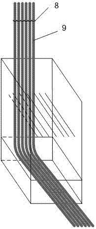
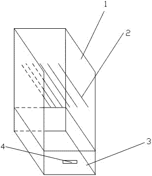
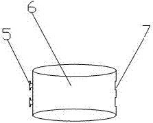
[0020] like Figure 1-3 As shown, a cable laying fixing device includes a cable branch trench and a cable fixing accessory. The cable branch trench is used for laying cables, and the cable fixing accessory is used to fix the cable. The upper side of the cable branch trench is not closed, and the cable branch trench There is a fixed cable partition, and there are a number of gaps evenly distributed from left to right in the fixed cable partition for the insertion and fixing of cables. The door panel, the cable fixing accessory includes a fixed ring sleeve, a through hole for connecting with the cable is provided in the middle of the fixed ring sleeve, a buckle is provided on one side of the fixed ring sleeve, and a slot matching the buckle is provided on the other side. The fixed ring sleeve is connected with the card slot of the adjacent fixed...


PUM


Abstract

The invention relates to a cable laying and fixing apparatus. The cable laying and fixing apparatus comprises a cable branch trench and one or more cable fixing auxiliary parts; the upper side surface of the cable branch trench is not sealed; a cable fixing partition plate is arranged in the cable branch trench; multiple gaps for placing and fixing cables are uniformly distributed in the cable fixing partition plate from left to right at intervals; a nick is formed in the lower part of the front side surface of the cable branch trench; a door plate used for opening and closing the nick is formed in the nick; each cable fixing auxiliary part comprises a fixing annular sleeve; a through hole for sleeving the corresponding cable is formed in the middle part of the fixing annular sleeve; buckles are arranged on one side of the fixing annular sleeve while clamping grooves matched with the buckles are formed in the other side; and one fixing annular sleeve is connected with the clamping grooves of the adjacent fixing annular sleeve through the buckle in a buckling manner. The cable laying and fixing apparatus is simple in structure, reasonable in design, and capable of realizing tidy laying of cables; and in addition, the cable gaps are tidy and unified, so that plugging is prevented conveniently, and entering of moisture of the cable branch trench to the box cabinet along the cable gaps can be prevented.

Description

technical field [0001] The invention relates to a cable laying and fixing device. Background technique [0002] In the power system, substations need to lay a large number of cables, especially low-voltage cables, mainly control cables. These cables are laid into the cabinet through the cable trench and its branch trench. The existing cable trench is a square structure. For the cables laid through the branch trench, especially low-voltage cables, they are simply fixed in the branch trench with binding tapes, metal wires, etc., or they are not fixed, and they are directly inserted into the cabinet and then placed in the cabinet. Fixing, the overall layout is messy, because many cables are bundled into the cabinet and it is difficult to effectively seal the gap between the cables, so that the moisture in the cable branch channel enters the cabinet along the cable gap, which seriously affects the moisture resistance of the cabinet Effect. Contents of the invention [0003]...

Claims


Application Information

Patent Timeline
IPC IPC(8): H02B1/20H02G9/02
CPCH02B1/202H02G9/02
Inventor 孙亚辉宋微浪
Owner STATE GRID FUJIAN ELECTRIC POWER CO LTD
Why Eureka
Try Eureka