Power box protection apparatus

A protection device and power box technology, applied in electrical components, chassis/cabinet/drawer parts, electrical equipment shell/cabinet/drawer, etc., can solve problems such as inability to control the temperature of the power box and affecting power components

Inactive Publication Date: 2017-12-19
王静娴
View PDF5 Cites 2 Cited by
  • Summary
  • Abstract
  • Description
  • Claims
  • Application Information

AI Technical Summary

Problems solved by technology

[0005] In order to overcome the existing power box, the present invention can place power components, but cannot control the temperature in the power box, and when the temperature is too high or too low, it will affect the use of power components. The technology to be solved by the present invention The problem is to provide a power box protection device that can not tightly place power components and can also control the temperature in the power box, thereby preventing the use of power components from being affected when the temperature is too high or too low

Method used


Image

  • Power box protection apparatus
  • Power box protection apparatus
  • Power box protection apparatus

Examples


Embodiment 1

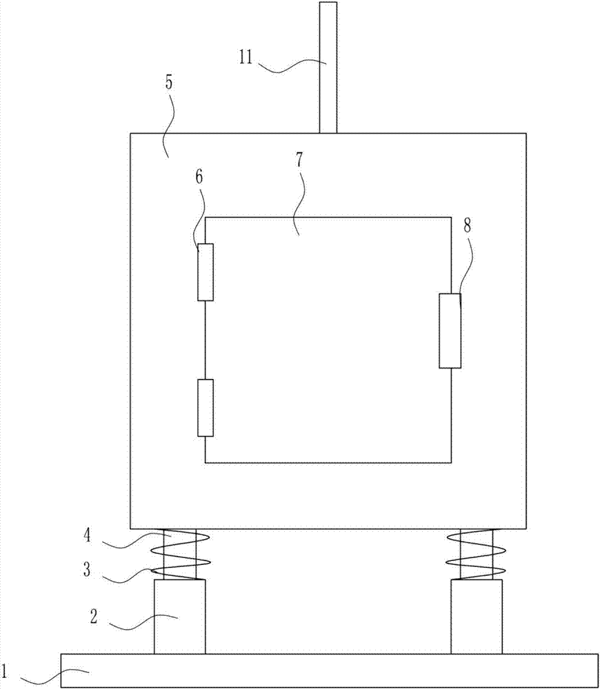
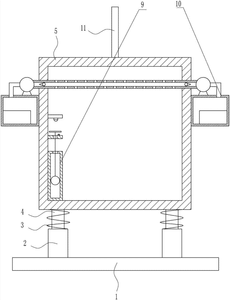
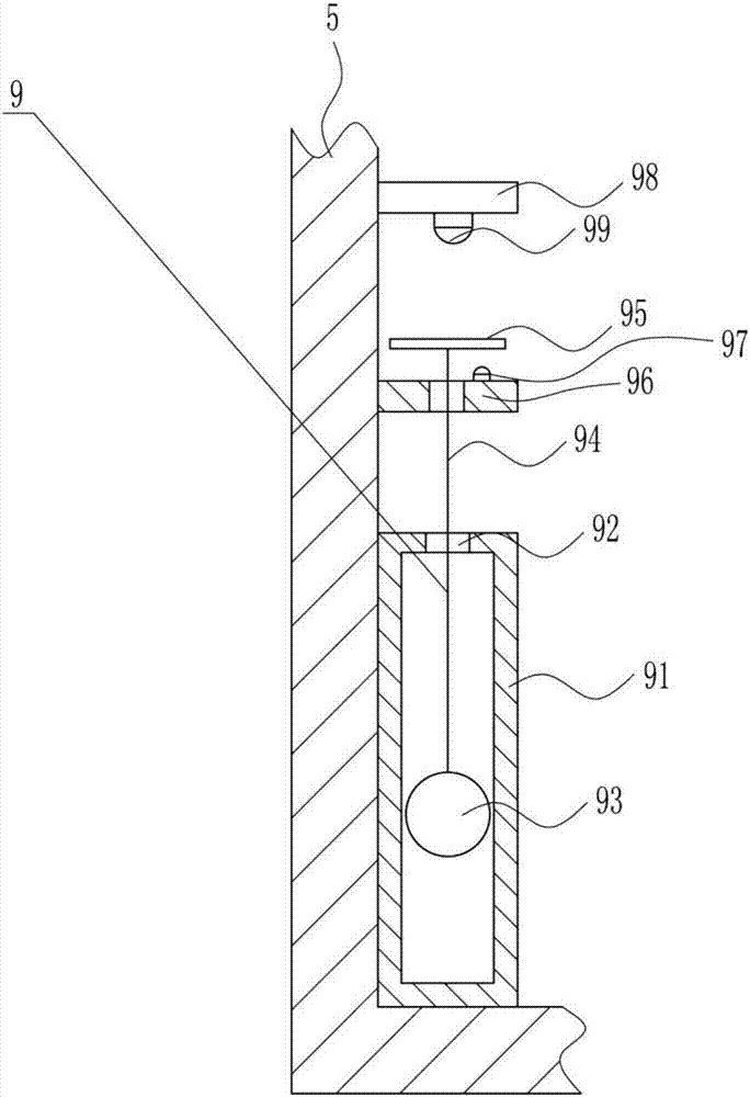
[0040] A power box guard such as Figure 1-10 As shown, it includes a bottom plate 1, a sleeve 2, a spring 3, a movable rod 4, an electric box 5, a hinge 6, a door 7, a handle 8, a temperature device 9, a temperature adjustment device 10 and a lightning rod 11, and the top of the bottom plate 1 is left and right A sleeve 2 is installed symmetrically on both sides, and a movable rod 4 is arranged inside the sleeve 2. A power box 5 is installed between the tops of the movable rods 4 on the left and right sides, and a spring is connected between the bottom of the power box 5 and the top of the sleeve 2. 3. A lightning rod 11 is installed in the middle of the top of the power box 5, and a box door 7 is installed in the middle of the front side of the power box 5. A hinge 6 is installed symmetrically on the left side of the box door 7, and the hinge 6 is connected to the front of the power box 5. The left side of the side is connected, the middle part of the right side of the box d...

Embodiment 2

[0042] A power box guard such as Figure 1-10 As shown, it includes a bottom plate 1, a sleeve 2, a spring 3, a movable rod 4, an electric box 5, a hinge 6, a door 7, a handle 8, a temperature device 9, a temperature adjustment device 10 and a lightning rod 11, and the top of the bottom plate 1 is left and right A sleeve 2 is installed symmetrically on both sides, and a movable rod 4 is arranged inside the sleeve 2. A power box 5 is installed between the tops of the movable rods 4 on the left and right sides, and a spring is connected between the bottom of the power box 5 and the top of the sleeve 2. 3. A lightning rod 11 is installed in the middle of the top of the power box 5, and a box door 7 is installed in the middle of the front side of the power box 5. A hinge 6 is installed symmetrically on the left side of the box door 7, and the hinge 6 is connected to the front of the power box 5. The left side of the side is connected, the middle part of the right side of the box d...

Embodiment 3

[0045] A power box guard such as Figure 1-10 As shown, it includes a bottom plate 1, a sleeve 2, a spring 3, a movable rod 4, an electric box 5, a hinge 6, a door 7, a handle 8, a temperature device 9, a temperature adjustment device 10 and a lightning rod 11, and the top of the bottom plate 1 is left and right A sleeve 2 is installed symmetrically on both sides, and a movable rod 4 is arranged inside the sleeve 2. A power box 5 is installed between the tops of the movable rods 4 on the left and right sides, and a spring is connected between the bottom of the power box 5 and the top of the sleeve 2. 3. A lightning rod 11 is installed in the middle of the top of the power box 5, and a box door 7 is installed in the middle of the front side of the power box 5. A hinge 6 is installed symmetrically on the left side of the box door 7, and the hinge 6 is connected to the front of the power box 5. The left side of the side is connected, the middle part of the right side of the box d...


PUM


Abstract

The invention relates to a protection apparatus, particularly to a power box protection apparatus and aims to provide the power box protection apparatus which can place electric power parts as well as can perform temperature control to the exterior of power box to further prevent influence to use of the electric power parts caused by overhigh or over low temperatures by solving technical problems. For solving the technical problems, the invention provides the power box protection apparatus; the power box protection apparatus comprises a bottom plate, sleeves and the like; the sleeves are symmetrically mounted on the left and right sides of the top of the bottom plate; a movable rod is arranged in each sleeve; the power box is mounted between the top ends of the left and right movable rods; and springs are connected between the bottom of the power box and the top parts of the sleeves. By virtue of a pushing apparatus, the power box can be elevated, so that damage of the electric power parts caused by contact between the power box and water can be further prevented; and in addition, the provided power box protection apparatus can place the electric power parts as well as can perform temperature control to the exterior of power box to further prevent influence to use of the electric power parts caused by overhigh or over low temperatures.

Description

technical field [0001] The invention relates to a protective device, in particular to a protective device for an electric box. Background technique [0002] Power chassis are mostly used to load instruments, meters, electronics, communications, automation, sensors, smart cards, industrial control, precision machinery and other items. Most of the materials are high-quality aluminum alloy profiles. Aluminum alloy profiles have firm structure, beautiful appearance, and good heat dissipation. And other characteristics, it is an ideal box for high-end instruments. [0003] In order to protect the safe use of electronic components and prevent damage, the electrical components will be put into the power box for protection. However, the existing power box only has the function of placing power components, and cannot control the temperature inside the power box. , and when the temperature is too high or too low, it will affect the use effect of the power components. Therefore, it is...

Claims


Application Information

Patent Timeline
Patent Type & Authority Applications(China)
IPC IPC(8): H05K7/20H05K5/02
CPCH05K7/20H05K5/0217H05K5/0234H05K5/0247H05K7/20209
Inventor 王静娴欧阳欢苏景容
Owner 王静娴
Why Eureka
Try Eureka