
Pressurizing type necking machine

A shrinking and shrinking die technology, which is applied in metal processing equipment, forming tools, manufacturing tools, etc., can solve the problems of large capillary temperature drop, unfavorable capillary shrinking station, long action stroke, etc., and achieve the increase of shrinking pressure The effect of obvious pressure, simple equipment structure and fast response speed

Pending Publication Date: 2017-12-22
BEIJING JINGCHENG RUIXINCHANGCAI ENG TECH +1
View PDF0 Cites 0 Cited by
  • Summary
  • Abstract
  • Description
  • Claims
  • Application Information

AI Technical Summary

Problems solved by technology

The problem of the former is that the position of the fixed claw remains unchanged, which is not conducive to the entry of the capillary into the necking station; the latter overcomes the disadvantages of the former, but due to the laborious lever of the mechanism, the drive hydraulic cylinder with a large bore diameter is often selected, and the action stroke is long, resulting in equipment It is huge, requires a large hydraulic flow, and the rhythm of action is slow, which affects production efficiency and causes a large capillary temperature drop, which is not conducive to the smooth progress of pipe jacking

Method used


Image

  • Pressurizing type necking machine
  • Pressurizing type necking machine
  • Pressurizing type necking machine

Examples


Embodiment Construction

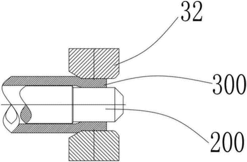
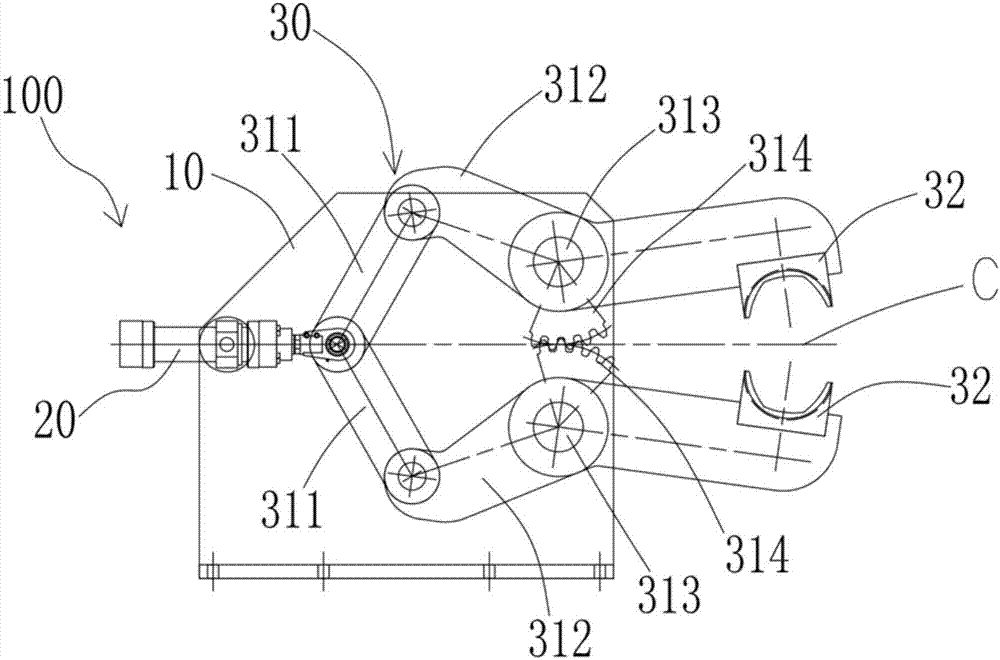
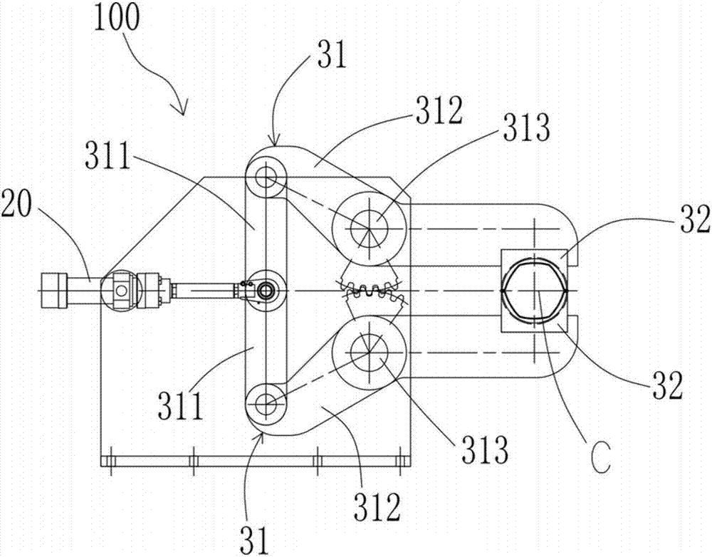
[0050] The details of the present invention can be understood more clearly with reference to the accompanying drawings and the description of specific embodiments of the present invention. However, the specific embodiments of the present invention described here are only for the purpose of explaining the present invention, and should not be construed as limiting the present invention in any way. Under the teaching of the present invention, the skilled person can conceive any possible modification based on the present invention, and these should be regarded as belonging to the scope of the present invention.

[0051] Please refer to Figure 1 to Figure 13, the present invention proposes a pressurized necking machine 100, which at least includes a frame 10, a hydraulic cylinder 20 mounted on the frame 10, and a synchronous swing unit 30, the synchronous swing unit 30 includes Two swing assemblies 31, each swing assembly 31 all comprises pull rod 311, swing arm 312, mandrel 313 ...


PUM


Abstract

The invention provides a pressurizing type necking machine and relates to the technical field of steel rolling devices. The pressurizing type necking machine at least comprises a machine frame, a hydraulic cylinder and a synchronous swinging unit, wherein the hydraulic cylinder and the synchronous swinging unit are installed on the machine frame. The synchronous swinging unit comprises two swinging assemblies. Each swinging assembly comprise a pull rod, a swing arm, a mandrel and a sector tooth, wherein the swinging arm is hinged to the machine frame through the mandrel, one end of the swinging arm is hinged to the pull rod, the other end of the swinging arm is provided with a necking die, one end of the pull rod is hinged to a cylinder head of the hydraulic cylinder, the other end of the pull rod is hinged to the swinging arm, the sector tooth is arranged on the mandrel in a sleeving manner and fixedly connected with the swinging arm, an interval exists between the two swinging arms. The two sector teeth are mutually meshed. The two swinging assemblies are driven by the hydraulic cylinder to be synchronously opened and closed. The pressurizing type necking machine completes the necking action through one hydraulic cylinder, and the pressurizing type necking machine is simple structure and rapid in response.

Description

technical field [0001] The invention relates to the technical field of steel rolling equipment, in particular to a pressurized necking machine for producing seamless steel pipes. Background technique [0002] The working principle of the pipe jacking process is to push the ejector rod through the transmission rack, so that the capillary pipe after the pre-piercing mandrel has been shrunk is extended and rolled out of the waste pipe through multiple roller dies, so as to achieve the effect of diameter reduction, wall reduction and extension. Purpose. CPE is the abbreviation of Cross-roll Piercing and Elongation, and the CPE pipe jacking process is an improved pipe jacking process. The CPE pipe jacking process is to make the capillary pipe which is pre-pierced through the mandrel and the end is narrowed through multiple roller dies to achieve diameter reduction, wall reduction and extension, and then push out the waste pipe. In order to extend the hollow capillary in the pip...

Claims


Application Information

Patent Timeline
IPC IPC(8): B21D41/04B21D37/10
CPCB21D37/10B21D41/04
Inventor 丁军胡晓军徐刚贾庆春张娜
Owner BEIJING JINGCHENG RUIXINCHANGCAI ENG TECH
Learn More