Movable pole derrick equipment

A mobile, rod-picking technology, used in cranes, transportation and packaging, etc., can solve problems such as poor flexibility, need attention, and no running function, and achieve the effect of improving stability

Active Publication Date: 2017-12-22
GUANGDONG PANGYUAN ENG MACHINERY
View PDF8 Cites 6 Cited by
  • Summary
  • Abstract
  • Description
  • Claims
  • Application Information

AI Technical Summary

Problems solved by technology

[0002] During building construction, when tower cranes are dismantled, when components need to be reversed between floors or other components need to be hoisted, they will choose to install auxiliary winches. The traditional installation of auxiliary winches is to use wall-inserted bolts to fix the fixed winch on the floor, and then find a high Point-made simple cantilever rods are installed to fix the pulleys, and the hoisting rope is wound around the pulleys to assist the hoisting construction. This method has disadvantages, that is, the use of wall-inserted bolts destroys the floor structure, and the hole needs to be filled later. When there is no suitable commanding height, the installation will not be possible. The cantilever rod, and the fixing method and stability of the cantilever rod need to be paid attention to. It needs to be re-fixed when the hoisting position needs to be moved, which is labor-intensive
[0003] Patent No. 201020516487.6, a utility model patent for a pole crane, discloses a pole crane with strong adaptability, which includes a fixed seat, a boom, a wire rope, a lifting block and a counterweight device, and the fixed seat is composed of a main It consists of a seat and a front seat post perpendicular to it. A counterweight device is provided at the rear end of the main seat. The bottom of the boom is hinged to the pin shaft of the front seat and can rotate around the front seat post. The top of the boom is equipped with cross-shaped top lugs that are perpendicular to each other. , the ear plate is provided with four plate holes, of which the plate holes on both sides are respectively connected and tightened with the ear plates at both ends of the front seat post through steel wire ropes and chain hoists, forming a stable triangular system, and the rear side plate holes are passed through The steel wire rope, fixed pulley and chain hoist are respectively connected and tightened with the rear and middle connecting ear plates of the main seat to form another stable triangular system perpendicular to the above triangular system, which is composed of the front side plate hole and the lifting block Therefore, it has the characteristics of safety and stability, low cost, and strong adaptability in engineering, but it does not have the function of walking, and it is troublesome to move, and its boom is fixed and different in length. There is a problem of poor flexibility in

Method used


Image

  • Movable pole derrick equipment
  • Movable pole derrick equipment
  • Movable pole derrick equipment

Examples


Embodiment Construction

[0024] The following will clearly and completely describe the technical solutions in the embodiments of the present invention with reference to the accompanying drawings in the embodiments of the present invention. Obviously, the described embodiments are only some, not all, embodiments of the present invention.

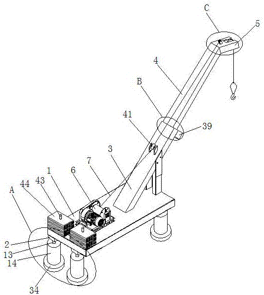
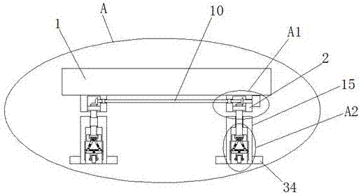
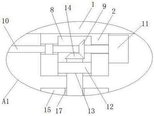
[0025] refer to Figure 1-7, a mobile lifting pole equipment, including a base 1, the four corners of the bottom of the base 1 are provided with a support module supporting the base 1, the support module includes four fixed seats 2 fixedly installed at the four corners of the bottom of the base 1, and The supporting module is equipped with a walking module that is convenient for the movement of the base 1. The top of the base 1 is fixedly and obliquely installed with a fixed boom 3. The end of the fixed boom 3 away from the base 1 is provided with a movable boom 4. The movable boom 4 is far away from the fixed boom. One end of the 3 is welded with a square fixed bloc...


PUM


Abstract

The invention discloses movable pole derrick equipment. The movable pole derrick equipment comprises a base, wherein support modules for supporting the base are arranged at the four corners of the bottom of the base; each support module comprises four fixed seats fixedly installed at the four corners of the bottom of the base, and a travelling module facilitating the base to move is arranged on the support module; a fixed boom is fixedly installed slantwise at the top of the base; a movable boom is arranged at one end away from the base, of the fixed boom; a square fixing block is welded to one end away from the fixed boom, of the movable boom; a winch fixedly installed at the top of the base is arranged at one side of the fixed boom; and a steel wire rope is connected between the winch and the square fixing block. According to the movable pole derrick equipment disclosed by the invention, the stability of the base during the movement of the equipment can be improved through the travelling modules, and the stability of the base during the running of the equipment can be improved through the support modules; and moreover, the telescopic movable boom is capable of improving the flexibility of the equipment.

Description

technical field [0001] The invention relates to the technical field of construction engineering, in particular to a mobile lifting pole equipment. Background technique [0002] During building construction, when tower cranes are dismantled, when components need to be reversed between floors or other components need to be hoisted, they will choose to install auxiliary winches. The traditional installation of auxiliary winches is to use wall-inserted bolts to fix the fixed winch on the floor, and then find a high Make a simple cantilever rod to install the fixed pulley, and the hoist rope is wound around the pulley to assist the hoisting construction. This method has shortcomings, that is, the wall bolts are used to damage the floor structure, and the hole needs to be filled later. When there is no suitable commanding height, the installation will not be possible. The cantilever rod, and the fixing method and stability of the cantilever rod need to be paid attention to. It nee...

Claims


Application Information

Patent Timeline
Patent Type & Authority Applications(China)
IPC IPC(8): B66C23/04B66C23/687B66C23/78
CPCB66C23/04B66C23/706B66C23/78B66C2700/0392
Inventor 姚平社李丽吴世超
Owner GUANGDONG PANGYUAN ENG MACHINERY
Why Eureka
Try Eureka