Pulley block for hook bridge crane

A technology of bridge cranes and pulley blocks, which is applied in the direction of load hanging components, portable lifting devices, hoisting devices, etc., which can solve the problems of reducing the service life of steel cables, damage to steel cable friction, and tilting of pulley blocks, etc., to increase winding way, reduce position swing, reduce wear effect

Active Publication Date: 2019-08-13
TAIZHOU TENGFA BUILDING MACHINERY
View PDF6 Cites 0 Cited by
  • Summary
  • Abstract
  • Description
  • Claims
  • Application Information

AI Technical Summary

Problems solved by technology

[0002] The pulley block is composed of several fixed pulleys, movable pulleys and ropes passing through them. It is a simple lifting tool for labor saving and speed change, and is also one of the indispensable parts of lifting machinery. During the process, due to the change of the force state and the winding form of the pulley block, the pulley block will tilt, causing friction damage to the cable and reducing the service life of the cable

Method used


Image

  • Pulley block for hook bridge crane
  • Pulley block for hook bridge crane
  • Pulley block for hook bridge crane

Examples


Embodiment

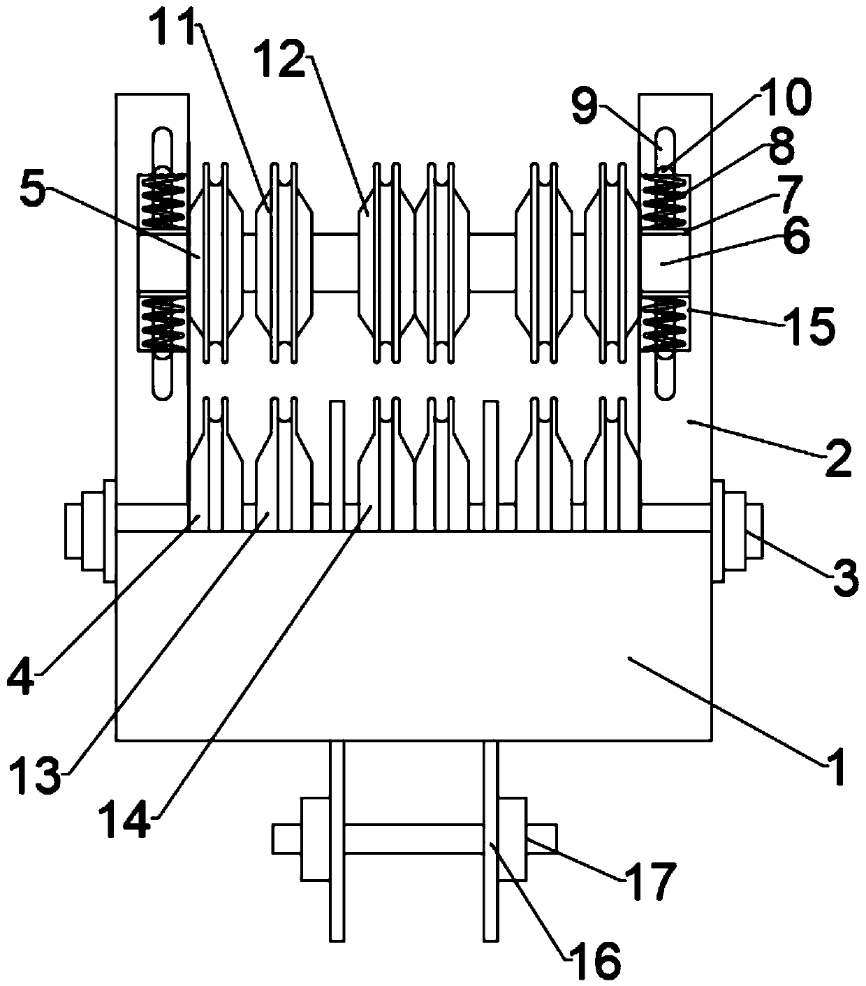
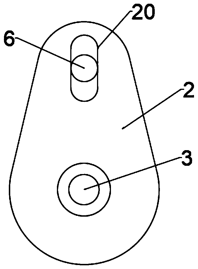
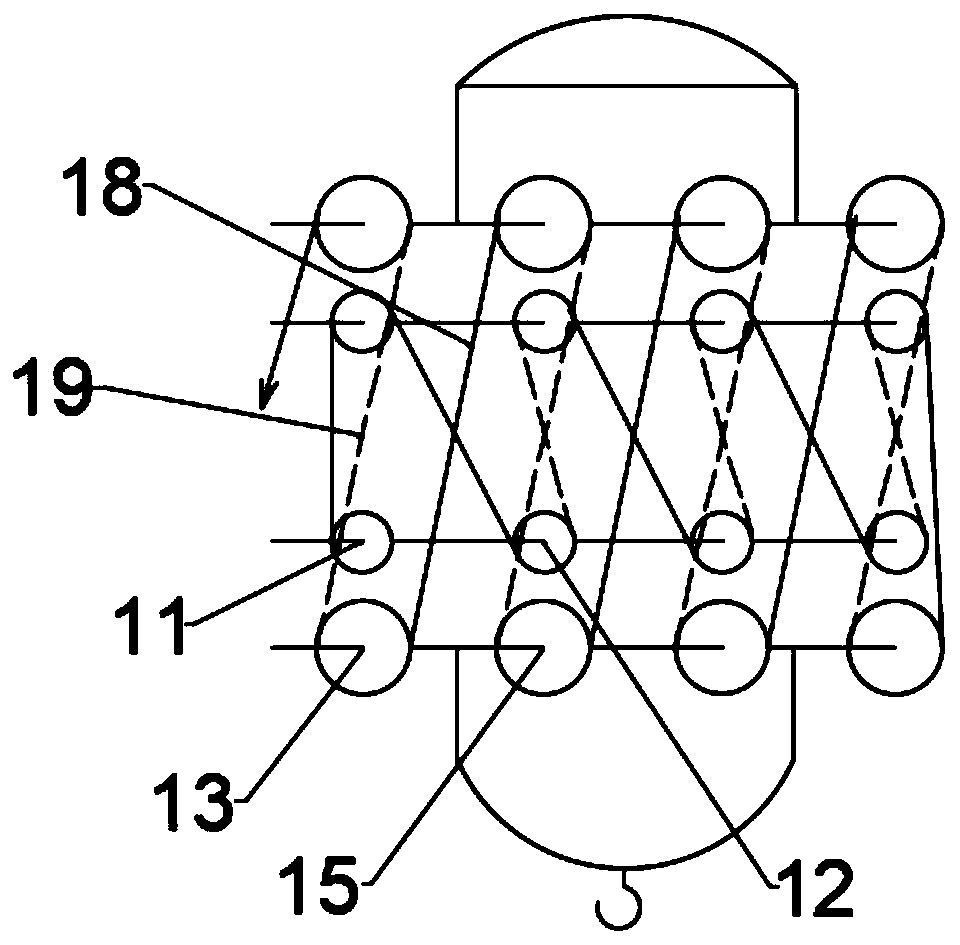
[0019] Such as figure 1 and figure 2 As shown, the present invention provides a pulley block for a hook bridge crane, comprising an outer casing 1 and a side wall 2, the semicircular outer casing 1 is set on the bottom of the side wall 2, and the side The outer wall at the top of the wall 2 is provided with a limiting groove 20, and the inner wall of the side wall 2 is provided with a rectangular elastic cavity 15, and the limiting groove 20 communicates with the elastic cavity 15, and the bottom and top of the side wall 2 The main shaft 3 and the secondary shaft 6 are installed horizontally in the middle, the main and auxiliary wheels 4 are installed at both ends of the main shaft 3, and the main line wheel C13 is installed on the inner side of the main line wheel 4, and the combination line is set on the inner side of the main line wheel C13. Wheel D14, hook side plates 16 are installed at both ends of the combined wire wheel, the hook side plates 16 longitudinally penetra...


PUM


Abstract

The invention discloses a pulley block for an overhead crane with hook. The pulley block comprises an outer protective shell and side walls, wherein the semi-circular outer protective shell is mounted at the bottoms of the side walls in a sleeving manner; limiting grooves are formed in the outer walls of tops of the side walls; rectangular springing cavities are formed in the inner walls of the side walls and communicate with the limiting grooves; a primary shaft and a secondary shaft are transversely mounted in middles of bottoms and tops of the side walls; main auxiliary wheels are mounted at two ends of the primary shaft; main reels C are mounted on the inner sides of the main auxiliary wheels; combined reels D are mounted on the inner sides of the main reels C in a sleeving manner; lifting hook side plates are mounted at two ends of the combined reels and longitudinally penetrate through the bottom of the outer protective shell; two ends of the secondary shaft are mounted in the limiting grooves in a sleeving manner; a shaft sleeve ring is mounted at the part, in the springing cavities, of the secondary shaft in a sleeving manner; T-shaped rods are mounted at the top and the bottom of the shaft sleeve ring; springs are mounted on the T-shaped rods in a sleeving manner; secondary auxiliary wheels are mounted at two ends of the secondary shaft in a sleeving manner; small rollers A are arranged on the inner sides of the secondary auxiliary wheels; and combined rollers B are arranged on the inner sides of the small rollers A. The composability is high and steel cable connection is stable.

Description

technical field [0001] The invention relates to the technical field of cranes, in particular to a pulley block for hook bridge cranes. Background technique [0002] The pulley block is composed of several fixed pulleys, movable pulleys and ropes passing through them. It is a simple lifting tool for labor saving and speed change, and is also one of the indispensable parts of lifting machinery. During the process, due to the change of the force state and the winding form of the pulley block itself, the pulley block tilted, resulting in damage to the cable friction and reducing the service life of the cable. Contents of the invention [0003] In order to overcome the deficiencies of the existing technical solutions, the present invention provides a pulley block for a hook bridge crane, which not only reduces the swing of the steel cable during the hoisting process from the arrangement of the pulley block and the installation structure, but also through the set pulley combinat...

Claims


Application Information

Patent Timeline
Patent Type & Authority Patents(China)
IPC IPC(8): B66D3/08B66C13/06
CPCB66C13/06B66D3/08
Inventor 苗则波
Owner TAIZHOU TENGFA BUILDING MACHINERY
Why Eureka
Try Eureka