Perforating device for monitor installation

A drilling device and a technology for installation, applied in the direction of supporting devices, drilling equipment and methods, chemical instruments and methods, etc., can solve the problems of slow drilling speed, time-consuming and laborious, etc.

Inactive Publication Date: 2017-12-22
吴义锖
View PDF6 Cites 15 Cited by
  • Summary
  • Abstract
  • Description
  • Claims
  • Application Information

AI Technical Summary

Problems solved by technology

[0006] In order to overcome the shortcomings of time-consuming and labor-intensive, slow punching speed and manual cleaning of punching equipment after punching, the present invention aims to solve the technical problem of providing a time-saving, labor-saving, A punching device for monitor installation that has a fast punching speed and can clean the punched parts

Method used


Image

  • Perforating device for monitor installation
  • Perforating device for monitor installation
  • Perforating device for monitor installation

Examples


Embodiment 1

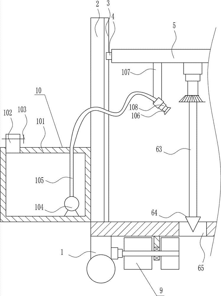
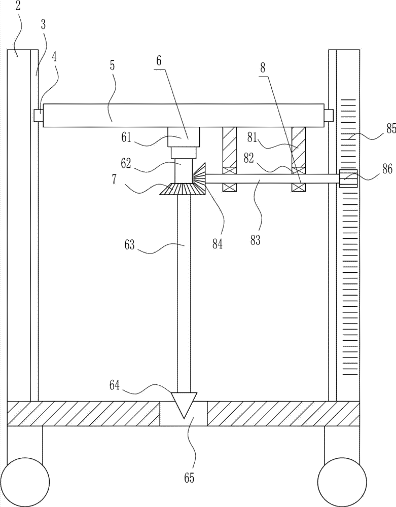
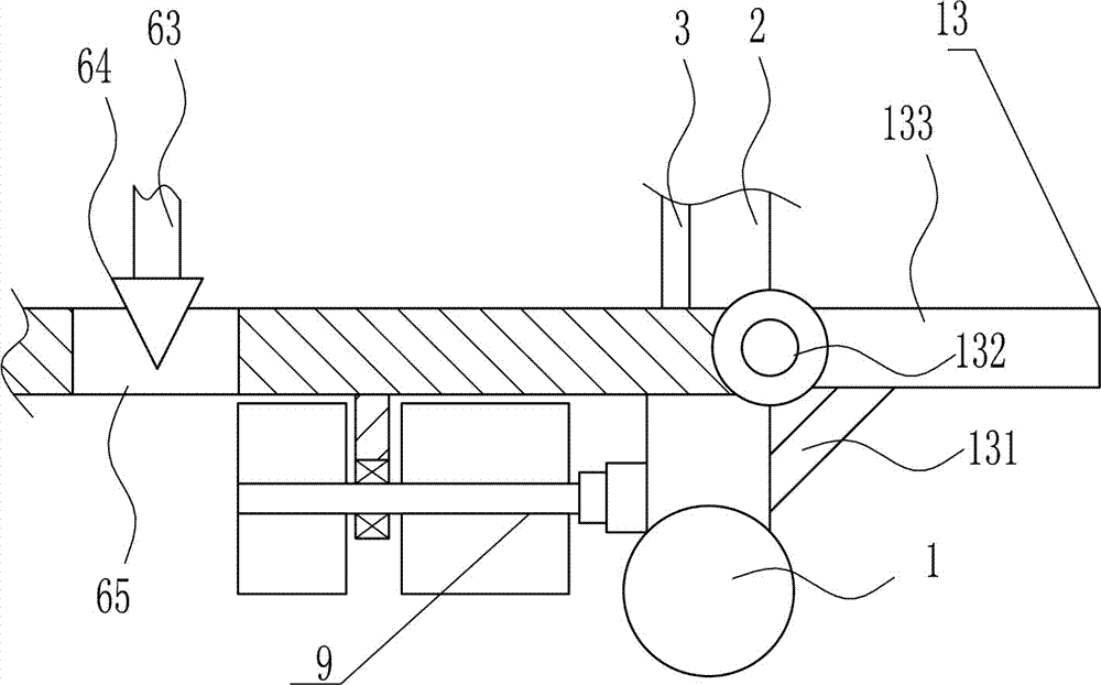
[0039] A perforating device for monitor installation, such as Figure 1-8 As shown, it includes a trolley 1, a first support plate 2, a slide rail 3, a slider 4, a horizontal plate 5, a punching mechanism 6, a first bevel gear 7 and a moving device 8, and the left and right sides of the top of the trolley 1 are symmetrical The first support plate 2 is installed in the type, and the inner surface of the first support plate 2 on the left and right sides is equipped with a slide rail 3. The slide rail 3 is vertically arranged, and the slide rail 3 is provided with a slider 4. The rail 3 is slidably matched, and a horizontal plate 5 is installed between the right side of the left slider 4 and the left side of the right slider 4, and a punching mechanism 6 is arranged in the middle of the bottom of the horizontal plate 5, and the punching part of the punching mechanism 6 Located in the middle of the cart 1, the punching mechanism 6 is connected with the first bevel gear 7, and a mo...

Embodiment 2

[0041] A perforating device for monitor installation, such as Figure 1-8 As shown, it includes a trolley 1, a first support plate 2, a slide rail 3, a slider 4, a horizontal plate 5, a punching mechanism 6, a first bevel gear 7 and a moving device 8, and the left and right sides of the top of the trolley 1 are symmetrical The first support plate 2 is installed in the type, and the inner surface of the first support plate 2 on the left and right sides is equipped with a slide rail 3. The slide rail 3 is vertically arranged, and the slide rail 3 is provided with a slider 4. The rail 3 is slidably matched, and a horizontal plate 5 is installed between the right side of the left slider 4 and the left side of the right slider 4, and a punching mechanism 6 is arranged in the middle of the bottom of the horizontal plate 5, and the punching part of the punching mechanism 6 Located in the middle of the cart 1, the punching mechanism 6 is connected with the first bevel gear 7, and a mo...

Embodiment 3

[0044] A perforating device for monitor installation, such as Figure 1-8 As shown, it includes a trolley 1, a first support plate 2, a slide rail 3, a slider 4, a horizontal plate 5, a punching mechanism 6, a first bevel gear 7 and a moving device 8, and the left and right sides of the top of the trolley 1 are symmetrical The first support plate 2 is installed in the type, and the inner surface of the first support plate 2 on the left and right sides is equipped with a slide rail 3. The slide rail 3 is vertically arranged, and the slide rail 3 is provided with a slider 4. The rail 3 is slidably matched, and a horizontal plate 5 is installed between the right side of the left slider 4 and the left side of the right slider 4, and a punching mechanism 6 is arranged in the middle of the bottom of the horizontal plate 5, and the punching part of the punching mechanism 6 Located in the middle of the cart 1, the punching mechanism 6 is connected with the first bevel gear 7, and a mo...


PUM


Abstract

The invention relates to a perforating device, in particular to a perforating device for monitor installation. The perforating device for monitor installation achieves the technical purposes of saving time and labor and being high in perforating speed and capable of cleaning perforating components. In order to achieve the technical purposes, the perforating device for monitor installation comprises a trolley, first supporting plates, sliding rails, sliding blocks, a transverse plate, a perforating mechanism and the like; the first supporting plates are symmetrically installed on the left and right sides of the top of the trolley, the sliding rails are installed on the inner side faces of the first supporting plates on the left and right sides, the sliding rails are vertically arranged, the sliding blocks are arranged on the sliding rails, the sliding blocks and the sliding rails are in sliding fit, and the transverse plate is installed between the left side face of the sliding block on the right side and the right side face of the sliding block on the left side. According to the cleaning device, perforating components can be cleaned and are longer in service life, and the device achieves the effects of saving time and labor and being high in perforating speed and capable of cleaning the perforating components.

Description

technical field [0001] The invention relates to a punching device, in particular to a punching device for installing a monitor. Background technique [0002] Architecture is the general term for buildings and structures, and it is an artificial environment created by people using the material and technological means they have mastered, and using certain scientific laws, feng shui concepts, and aesthetic principles to meet the needs of social life. [0003] Monitoring: Interpreted as monitoring and detection. Supervise, monitor, monitor and supervise. Test, the meaning of test measurement test. [0004] In the building monitoring, the monitor will be put into the ground to monitor the ground, but the monitor needs to be drilled into the hole, and the manual drilling of the ground is time-consuming, laborious and slow. , after punching, the punching equipment needs to be manually cleaned, so it is urgent to develop a time-saving and labor-saving, fast punching, and a punchi...

Claims


Application Information

Patent Timeline
Patent Type & Authority Applications(China)
IPC IPC(8): E21B7/02E21B15/00B08B3/02
CPCE21B7/02B08B3/02E21B15/00
Inventor 魏学林易宇情陈思蓉杨周
Owner 吴义锖
Why Eureka
Try Eureka