Fluid separating device, shaft structure and petroleum or natural gas producing method

A separation device and fluid channel technology, which is applied in the development of fluid, valve device of wellbore/well, and earth-moving drilling, etc., can solve problems such as affecting the efficiency of oil or natural gas extraction, and achieve improved extraction efficiency, continuous production, increased The effect of the flow area

Active Publication Date: 2017-12-22
成都百胜野牛科技有限公司
View PDF9 Cites 4 Cited by
  • Summary
  • Abstract
  • Description
  • Claims
  • Application Information

AI Technical Summary

Problems solved by technology

But this greatly affects the efficiency of oil or natural gas extraction

Method used


Image

  • Fluid separating device, shaft structure and petroleum or natural gas producing method
  • Fluid separating device, shaft structure and petroleum or natural gas producing method
  • Fluid separating device, shaft structure and petroleum or natural gas producing method

Examples


Embodiment 1

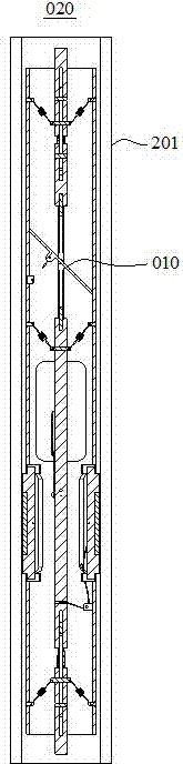
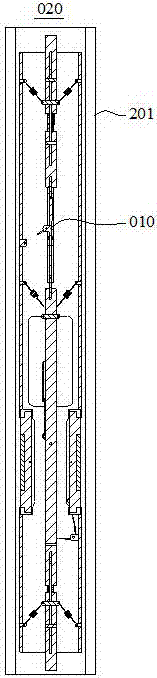
[0063] Please refer to figure 1 and figure 2 , figure 1 A working state diagram of the hoistway structure 020 provided in this embodiment, figure 2 Another working state diagram of the hoistway structure 020 provided in this embodiment. From figure 1 and figure 2 It can be seen from the figure that in this embodiment, the hoistway structure 020 includes a hoistway 201, and upper impact devices 202 ( Figure 9a-9c shown in ) and the lower impact device 203 ( Figure 10a-Figure 10c shown in ) and the fluid separation device 010 disposed in the hoistway 201. The fluid separation device 010 slides in the vertical direction in the hoistway 201 . When the fluid separation device 010 moves to the upper end of the shaft 201 , the fluid separation device 010 collides with the upper impact device 202 . When the fluid separation device 010 moves to the lower end of the shaft 201 , the fluid separation device 010 collides with the lower impact device 203 .

[0064] The fluid s...

Embodiment 2

[0089] This embodiment provides an oil or natural gas production method, which is realized based on the shaft structure 020 described in Embodiment 1. When the fluid separation device 010 is descending, the outlet of the shaft 201 is opened.

[0090] During the downward process of the fluid separation device provided in the related art, there is a relatively large frictional force between the partition and the inner wall of the shaft, and the upward flow of oil or natural gas under the fluid separation device exerts an upward thrust on the fluid separation device. Under the combined action of friction, upward thrust, and fluid resistance of oil or natural gas, the fluid separation device goes down slowly, or even cannot go down at all. In order to make the fast fluid separation device go down or speed up the downward speed of the fluid separation device, in the related art, when the fluid separation device is going down, it is necessary to close the outlet of the well to balanc...


PUM


Abstract

The invention relates to the technical field of oil and gas production, and discloses a fluid separating device, a shaft structure and a petroleum or natural gas producing method. By means of the fluid separating device and the shaft structure, the requirement for the hitting force of the fluid separating device and a lower hitting device is lowered, a mandrel can be switched between an opened position and a closed position only with small hitting force between the fluid separating device and the lower hitting device, and the reliability of the fluid separating device and the shaft structure in working is improved. By means of the method, the exit of a shaft is opened when the fluid separating device goes down, petroleum or natural gas can still be sprayed out of the shaft when the fluid separating device goes down, the continuous production of petroleum or natural gas is achieved, and production efficiency is greatly improved.

Description

technical field [0001] The invention relates to the technical field of oil and gas exploitation, in particular to a fluid separation device, a shaft structure and a method for producing oil or natural gas. Background technique [0002] During the development of oil or natural gas wells, when the oil or natural gas production in the well is low, the oil or natural gas cannot lift a large amount of liquid to the surface, which will form a certain degree of liquid accumulation at the bottom of the well, thereby reducing the production capacity of the oil or natural gas well. Even cause oil or gas wells to stop blowing. [0003] A fluid separation device is provided in the related art. A plurality of partitions are arranged on the periphery of the fluid partition device, and these partitions are always in contact with the inner wall of the hoistway under the action of the elastic member to form a seal. In this way, the pressure generated by the fluid below the fluid separation...

Claims


Application Information

Patent Timeline
Patent Type & Authority Applications(China)
IPC IPC(8): E21B34/14E21B43/00
CPCE21B34/14E21B43/00
Inventor 刘瀚森唐勇张罡李军民张忠林刘树飞苏诗策易诚雄周华谭宇茜唐湉刘向美珂刘士吉陈俊宏周侗侗
Owner 成都百胜野牛科技有限公司
Why Eureka
Try Eureka