
Base plate bearing device

A technology for carrying devices and substrates, applied in nonlinear optics, instruments, optics, etc., can solve problems such as poor horizontal black lines, breaking, and aggravating friction, so as to reduce the risk of fragmentation and eliminate installation gaps.

Inactive Publication Date: 2017-12-22
BOE TECH GRP CO LTD +1
View PDF3 Cites 2 Cited by
  • Summary
  • Abstract
  • Description
  • Claims
  • Application Information

AI Technical Summary

Problems solved by technology

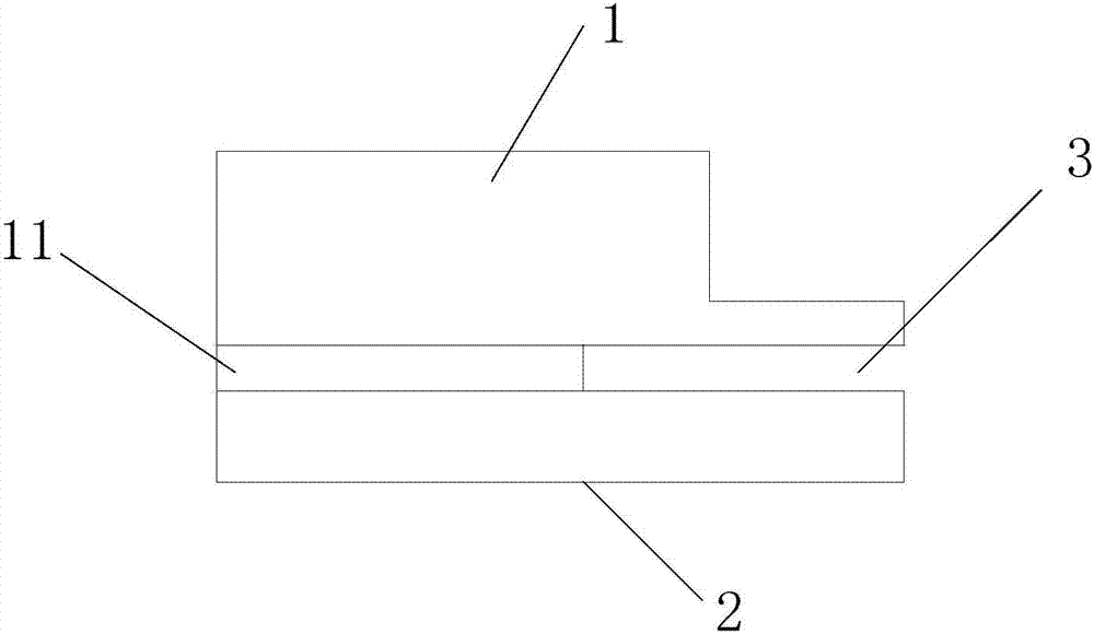
[0004] First, the first area of ​​the substrate cell 2 corresponding to the substrate surface has a planar structure in contact with the support member 1, and there is a boss 3 on the side corresponding to the connection between the support member 1 and the first area of ​​the substrate cell 2, namely After the support 1 is installed on the substrate unit 2, there is a gap 3 between the support 1 and the substrate unit 2, such as figure 1 As shown, coupled with the continuous thinning of the glass substrate, the situation that the glass substrate is inserted into the gap 3 between the substrate holder 2 and the support member 1 occurs from time to time, which will lead to the separation of the inner and outer frames of the carrier when the glass substrate is unloaded. and was pulled to pieces;
[0005] Second, the part of the support that is in contact with the surface of the glass substrate is a plane parallel to the surface of the glass substrate. During the transfer process, friction will occur between the support and the glass substrate, and the friction will change with the prolongation of the use time. The aggravation will cause certain damage to the substrate, and this situation will cause the Advanced Super Dimension Switching Technology (Advanced Super Dimension Switch, referred to as ADS) product level black line and other defects

Method used


Image

  • Base plate bearing device
  • Base plate bearing device
  • Base plate bearing device

Examples


Embodiment Construction

[0026] The features and principles of the present invention will be described in detail below with reference to the accompanying drawings. The examples cited are only used to explain the present invention and are not intended to limit the protection scope of the present invention.

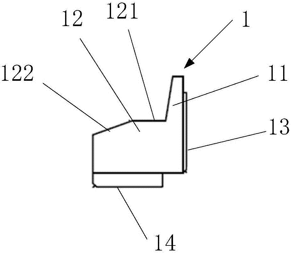
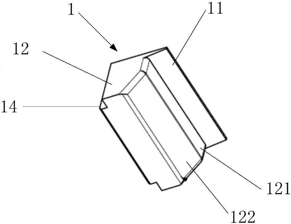
[0027] Such as Figure 2-Figure 8 As shown, this embodiment provides a substrate carrying device, including a carrying frame, a plurality of substrate pressing elements 2 are arranged around the carrying frame, an insulating support 1 is provided on the substrate pressing element 2, and the support 1 It includes a first portion 11 corresponding to the surface of the substrate and a second portion 12 corresponding to the side of the substrate. The substrate pressing element 2 includes a first region 21 corresponding to the surface of the substrate and a second region 22 corresponding to the side of the substrate. The first part 11 is embedded in the first area 21 and the second part 12 is fixedly conne...


PUM

PropertyMeasurementUnit
angleaaaaaaaaaa

Abstract

The invention relates to a base plate bearing device. The bearing device includes a load bearing frame, a plurality of base plate detaining units are arranged on the circumference of the load bearing frame, insulating support parts are arranged on the base plate detaining units, the insulating support parts comprise a first part corresponding to the surface of a base plate and a second part corresponding to the side face of the base plate, the base plate detaining units comprise a first area corresponding to the surface of the base plate and a second area corresponding to the side face of the base plate, the first part is arranged in the first area in an embedded mode, and the second part is fixedly connected to the second area. The base plate bearing device has the advantages that the first part of the support parts and the first area of the base plate detaining units are arranged in an embedded mode, the installation gap between the support parts and the base plate detaining units is eliminated, and the risk of fragmentation caused by the base plate being inserted into the gap is reduced.

Description

Technical field [0001] The invention relates to the technical field of liquid crystal product manufacturing, in particular to a substrate carrying device. Background technique [0002] Thin film deposition technology has a wide range of applications in many fields such as machinery, electronics, and semiconductors. At present, PVD (Physical Vapor Deposition) equipment generally adopts a vertical structure. The carrying device for carrying the glass substrate includes: an inner frame and an outer frame connected to the box. A plurality of substrate pressing elements are arranged around the outer frame. The support element is provided with a support for supporting the glass substrate, and the inner frame is provided with a support column for supporting the glass substrate, wherein the substrate is grounded (zero potential) and the cathode forms a potential difference, which facilitates the sputtering of target atoms to the glass On the substrate, which facilitates film formation. ...

Claims


Application Information

Patent Timeline
Patent Type & Authority Applications(China)
IPC IPC(8): G02F1/13
CPCG02F1/1303
Inventor 房伟华肖亮张勋泽蔡登刚段龙龙王健常浩
Owner BOE TECH GRP CO LTD
Learn More