Supercharge Your Innovation With Domain-Expert AI Agents!

Reactive power compensation method

A compensation method and power module technology, applied in reactive power compensation, reactive power adjustment/elimination/compensation, details of substation/switch layout, etc., can solve problems such as inability to target heat dissipation of power modules

Active Publication Date: 2017-12-22
广州亚申电气设备有限公司
View PDF4 Cites 3 Cited by
  • Summary
  • Abstract
  • Description
  • Claims
  • Application Information

AI Technical Summary

Problems solved by technology

[0005] Aiming at the technical problem that the existing reactive power compensation system cannot perform targeted heat dissipation on the power module, the present invention provides a reactive power compensation method with good heat dissipation

Method used


Image

  • Reactive power compensation method

Examples


Embodiment

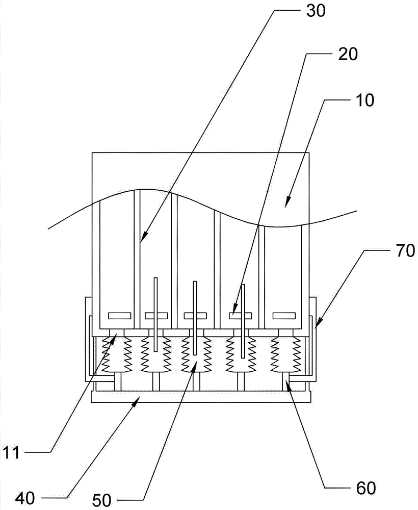
[0031] Embodiment: The reactive power compensation method includes the following content:

[0032] S1: The power module 20 generates a large amount of heat during use, causing the temperature of the cabinet 10 to increase, that is, the temperature of the heat dissipation space increases;

[0033] S2: The thermally conductive sheet 70 will transfer the temperature to the telescopic part. Because the telescopic part has the property of expanding when heated, the expansion part starts to expand after being heated, and the sealing plate moves upward under the push of the expansion part;

[0034] S3: The upward movement of the sealing plate causes the bellows 50 to shrink. After the bellows 50 shrinks, the silicone oil in the bellows will be squeezed out of the bellows 50, and the silicone oil enters the heat dissipation space under the push of the telescopic parts. The silicone oil is in contact with the power module 20 in the heat dissipation space;

[0035] S4: After the silicon oil dis...


PUM


Abstract

The invention belongs to the technical field of reactive power compensation, and provides a reactive power compensation method with good targeted heat dissipation in allusion to a technical problem that the existing reactive power compensation system cannot perform targeted heat dissipation on a power module. The reactive power compensation method comprises the content that S1, the power module generates a lot of heat in the using process, and the temperature of a cabinet is enabled to rise, that is, the temperature of a heat dissipation space rises; S2, a heat conducting piece transfers the temperature to a telescopic member, and the telescopic member has an attribute of thermal expansion, so that the telescopic member starts expanding after being heated, and a sealing plate moves upwards under the pushing of the telescopic member; S3, the upward movement of the sealing plate leads to contraction of a corrugated pipe, the corrugated pipe extrudes silicone oil in the corrugated pipe out of the corrugated pipe after contraction, the silicone oil gets into the heat dissipation space under the pushing of the telescopic member, and the silicone oil is contacted with the power module in the heat dissipation space; and S4, the temperature of the heat dissipation space corresponding to the power module drops after the silicone oil perform heat dissipation on the power module, and the heat transferred by the heat conducting piece to the telescopic member is reduced.

Description

Technical field [0001] The invention relates to the technical field of reactive power compensation, in particular to a reactive power compensation method. Background technique [0002] Reactive power compensation, the full name of reactive power compensation, is a technology that improves the power factor of the power grid in the power supply system, reduces the loss of power supply transformers and transmission lines, improves power supply efficiency, and improves the power supply environment. Therefore, the reactive power compensation device is in an indispensable and very important position in the power supply system. [0003] Air cooling or water cooling is generally used in specific applications. From the perspective of heat dissipation, water cooling is ideal. However, the water circulation system has high technological requirements, complicated installation, and heavy maintenance workload, and once water leaks, it will bring safety hazards. Therefore, when air cooling can...

Claims


Application Information

Patent Timeline
Patent Type & Authority Applications(China)
IPC IPC(8): H05K7/20H02B1/56H02J3/18
CPCY02E40/30H05K7/20927H02B1/565H02J3/18
Inventor 陈亮
Owner 广州亚申电气设备有限公司
Features
  • R&D
  • Intellectual Property
  • Life Sciences
  • Materials
  • Tech Scout
  • Unparalleled Data Quality
  • Higher Quality Content
  • 60% Fewer Hallucinations
Learn More