[0023] The technical solutions in the embodiments of the present invention will be clearly and completely described below in conjunction with the accompanying drawings in the embodiments of the present invention. Obviously, the described embodiments are only a part of the embodiments of the present invention, rather than all the embodiments. Based on the embodiments of the present invention, all other embodiments obtained by those of ordinary skill in the art fall within the protection scope of the present invention.
[0024] According to an embodiment of the present invention, a food processing centrifuge is provided.
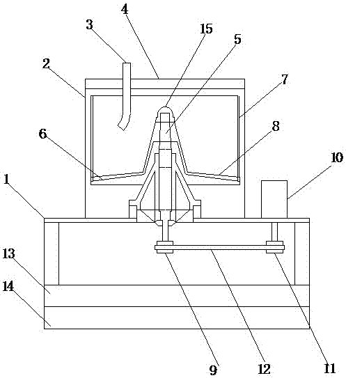
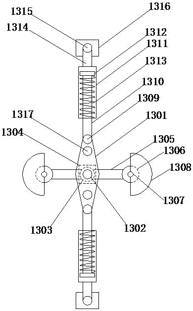
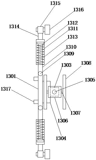
[0025] Such as Figure 1-4 As shown, the food processing centrifuge according to the embodiment of the present invention includes a frame 1, a casing 2, a feed port 3, an upper cover 4, a rotating spindle 5, a rotating drum 6, a rotating drum body 7, and a liquid baffle 8. , The driven wheel 9, the motor one 10, the driving wheel 11, the belt 12, the vibration mechanism 13, and the damping mechanism 14, wherein the upper end of the frame 1 is provided with the casing 2, and the upper end of the casing 2 is provided with As for the upper cover 4, the feed port 3 is provided on one side of the upper cover 4, and the rotating spindle 5 is provided in the middle position inside the casing 2, and the lower end of the rotating spindle 5 penetrates the frame 1 The end surface is fixedly connected to the center position of the driven wheel 9, the rotating main shaft 5 is provided with the rotating drum 6, and the upper end of the rotating drum 6 is provided with the liquid baffle 8 The drum body 7 is provided on the outer side, and the drum body 7 is a hollow structure. The upper side of the frame 1 is provided with the motor 10, and the output shaft of the motor 10 penetrates the frame 1 The upper end surface is fixedly connected to the center position of the driving wheel 11, the driven wheel 9 is connected to the driving wheel 11 through the belt 12, and the bottom end of the frame 1 is connected to the reducing device through the vibration mechanism 13 The vibration mechanism 14 is fixedly connected, and a power interface and a control switch are provided on the back of the rack 1.
[0026] The vibration mechanism 13 includes a movable plate 1301, a rotating shaft 1302, a movable block 1303, a fixed block 1304, a movable rod 1305, a motor two 1306, a rotating shaft 1307, an eccentric wheel 1308, a rotating shaft 1309, and a connecting rod 1310 , Movable groove 1311, limit block 1312, spring one 1313, connecting rod two 1314, rotating shaft four 1315, fixed frame 1316 and fixed shaft 1317, the intermediate position of the movable plate 1301 is interspersed with the rotating shaft 1302, the rotating shaft The bottom of a 1302 is fixedly connected to the movable block 1303 through the fixed block 1304. The movable rod 1305 is inserted through the bottom end of the movable block 1303, and the movable rod 1305 is connected to the movable plate 1301. The two ends of the movable rod 1305 are respectively provided with the second motor 1306, and the second motor 1306 is a bidirectional motor, and the output shafts at both ends of the second motor 1306 are connected to the eccentricity through the second shaft 1307. The position of the center of the wheel 1308 is fixedly connected. Both ends of the movable plate 1301 are respectively provided with the three shafts 1309, and the three shafts 1309 are movably connected with one end of the connecting rod 1310, and the other end of the connecting rod 1310 The limit block 1312 is provided and inserted into the inside of the movable groove 1311, and the connecting rod 1310 is located on the movable groove 1311 near the end of the rotating shaft 1309 and one of the limit blocks 1312 The first spring 1313 is arranged between the movable groove 1311, and the end of the movable groove 1311 away from the connecting rod 1310 is movably connected to the rotating shaft 1315 through the connecting rod two 1314, and the rotating shaft 1315 is arranged on the fixed frame At the upper end of 1316, the fixed shaft 1317 is provided at the upper end of the movable plate 1301 and inside the rotating shaft 3 1309, the upper end of the fixed shaft 1317 is fixedly connected to the bottom end of the frame 1, and the bottom end of the fixed frame 1316 is connected to The upper end of the damping mechanism 14 is fixedly connected, and the power interface is electrically connected to the control switch, the motor one 10, and the motor two 1306 respectively in sequence.
[0027] In one embodiment, for the above-mentioned rotating main shaft 5, the upper end of the rotating main shaft 5 is provided with a reinforcing hoop 15 so as to increase the service life of the rotating main shaft 5 and thereby improve the cost performance of the centrifuge.
[0028] In one embodiment, for the aforementioned shock-absorbing mechanism 14, the shock-absorbing mechanism 14 includes a supporting plate 1401, a supporting column 1402, a fixed block two 1403, a spring two 1404, a movable block two 1405, a connecting rod three 1406, The fixing ring 1407, the spring three 1408, the supporting rod 1409 and the supporting plate two 1410, wherein both sides of the lower end of the supporting plate 1401 are respectively movably linked by the through holes on the supporting column 1402 and the fixing block 1403, The lower end of the supporting column 1402 is inserted into the inner opening of the supporting plate two 1410, and the spring two 1404 is provided on the periphery of the supporting column 1402 and located between the supporting plate one 1401 and the second fixing block 1402. The bottom of the supporting plate 1401 and the inner ends of the supporting column 1402 are respectively provided with the fixing ring 1407, and the supporting rod 2 1409 is arranged between the two fixing blocks 1403, and the supporting rod 2 The middle position of 1409 is sleeved with the spring three 1408, both ends of the spring three 1408 are provided with the movable block two 1405, the movable block two 1405 is movably linked with the fixed ring 1407 through the connecting rod three 1406 As a result, the damping effect of the damping mechanism 14 is better, thereby improving the stability of the centrifuge, and thereby improving the separation quality of the centrifuge.
[0029] In one embodiment, for the above-mentioned spring 1313, the spring one 1313, the spring two 1404, and the spring three 1408 are all compression springs, and the spring one 1313 is provided to make the vibration mechanism 14 move more. Stable, thereby improving the separation efficiency of the centrifuge; by providing the spring two 1404 and the spring three 1408, the vibration damping effect of the vibration damping mechanism 14 is better, thereby improving the stability of the centrifuge, and thereby improving the separation quality of the centrifuge.
[0030] In one embodiment, for the above-mentioned spring two 1404, the elastic coefficient of the second spring 1404 is smaller than that of the spring three 1408, so that the vibration damping effect of the vibration damping mechanism 14 is better, thereby improving the performance of the centrifuge. Stability, thereby improving the separation quality of the centrifuge.
[0031] In one embodiment, for the aforementioned shock-absorbing mechanism 14, an elastic anti-skid pad is provided at the bottom of the shock-absorbing mechanism 14, so that relative sliding of the centrifuge will not occur during operation, thereby improving the stability of the centrifuge.
[0032] In one embodiment, for the above-mentioned movable plate 1301, the two eccentric wheels 1308 on the side of the movable plate 1301 are installed in the same direction, so that the vibrating mechanism 13 runs more stably, thereby enabling the centrifuge to separate food materials More fully, thereby improving the separation quality of the centrifuge.
[0033] In one embodiment, for the above-mentioned movable plate 1301, the two sets of eccentric wheels 1308 opposite to the two sides of the movable plate 1301 are installed in opposite directions, so that the vibration mechanism 13 runs more stably, thereby making the centrifuge separate food The raw materials are more sufficient, thereby improving the separation quality of the centrifuge.
[0034] In summary, with the above technical solution of the present invention, the vibration mechanism 13 is provided, so that when the food processing centrifuge is working, the centrifuge frame 1 and the casing 2 follow the movable plate 1301 on the vibration mechanism 13 Make regular vibrations, so that the food processing centrifuge can separate raw materials more fully, thereby improving the separation effect of the food processing centrifuge and improving the production efficiency of the enterprise; at the same time, the shock absorption mechanism 14 is set to make the food processing centrifuge operate during operation. There is no shaking caused by the vibration of the vibrating mechanism 13, so that the food processing centrifuge separates food materials more stably, while ensuring the separation effect and the separation rate, thereby improving the stability of the food processing centrifuge.
[0035] The above descriptions are only preferred embodiments of the present invention and are not intended to limit the present invention. Any modification, equivalent replacement, improvement, etc. made within the spirit and principle of the present invention shall be included in the present invention. Within the scope of protection.