Ferrite injection barrel and equipment thereof

A ferrite and material injection technology, applied in the field of machinery, can solve the problems of high equipment operating cost, high equipment manufacturing cost, poor energy-saving effect, etc., and achieve the effect of long service life, reducing operating energy consumption, and avoiding volatilization.

Active Publication Date: 2017-12-26
嘉兴天成强磁科技股份有限公司
View PDF17 Cites 0 Cited by
  • Summary
  • Abstract
  • Description
  • Claims
  • Application Information

AI Technical Summary

Problems solved by technology

[0005]1. The operating cost of the equipment is relatively high, resulting in a large amount of capital for the enterprise to invest in production
[0006]2. Poor energy saving effect
[0007]3. The manufacturing cost of equipment is relatively high

Method used


Image

  • Ferrite injection barrel and equipment thereof
  • Ferrite injection barrel and equipment thereof

Examples


Embodiment Construction

[0028] The present invention will be described in further detail below in conjunction with the accompanying drawings and specific embodiments.

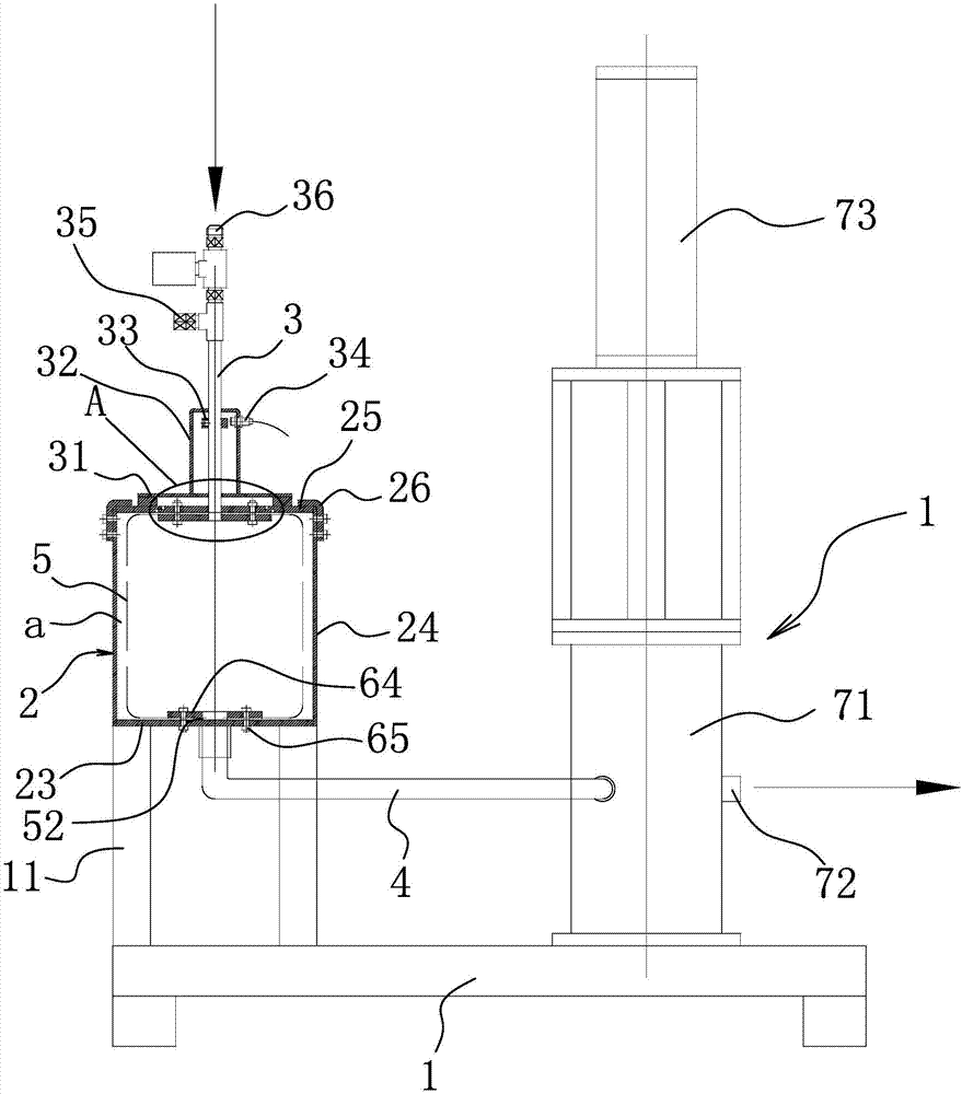
[0029] Such as figure 1 As shown, the ferrite injection bucket includes a base 1 on which a metal shell 2 with a cavity a is arranged, and the metal shell 2 and the base 1 are connected by a plurality of columns 11 distributed in an array.

[0030] The metal casing 2 includes a lower bottom plate 23 and a cylindrical body 24 whose lower end is sleeved in the circumferential direction of the lower bottom plate. An upper cover plate 25 is arranged on the upper end of the cylindrical body, and a positioning step is arranged on the lower surface of the upper cover plate circumferentially. The upper end of the cylindrical body is aligned with the positioning step fit.

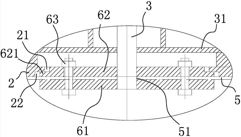
[0031] There are several L-shaped reinforcements 26 between the upper cover and the cylindrical body, the upper ends of the L-shaped reinforcements 26 are fastened on the ...


PUM


Abstract

The invention belongs to the technical field of machinery, and particularly relates to a ferrite injection barrel and equipment thereof. The ferrite injection barrel and the equipment thereof solve the problems of unreasonable design in the prior art and the like. The ferrite injection barrel comprises a base, a metal shell provided with a cavity is arranged on the base, a feeding pipe is connected to the top of the metal shell, a discharging pipe is connected to the bottom of the metal shell, a rubber liner fixed to the metal shell is arranged in the cavity, a feeding port communicating with the feeding pipe is formed in the rubber liner, and a discharging port communicating with the discharging pipe is further formed in the rubber liner. The ferrite injection barrel and the equipment thereof have the advantages that more energy is saved and the cost is lower.

Description

technical field [0001] The invention belongs to the technical field of machinery, and in particular relates to a ferrite injection barrel and equipment thereof. Background technique [0002] Ferrite is a strong magnetic raw material. [0003] At present, when the existing ferrite is injected into the mold, it is generally injected through injection equipment. The principle is as follows: the ferrite is transported into the material barrel through the feed end, and a stirring mechanism is set in the material barrel for timing or real-time stirring, which is mainly to ensure the quality of the ferrite output. [0004] There are following technical problems in the above-mentioned mode: [0005] 1. The operating cost of the equipment is relatively high, which leads to a large amount of capital invested by the enterprise in production. [0006] 2. Poor energy saving effect. [0007] 3. The manufacturing cost of the equipment is relatively high. Contents of the invention ...

Claims


Application Information

Patent Timeline
IPC IPC(8): B65D88/54B65D90/04B65D90/08B65D90/12
CPCB65D88/54B65D90/04B65D90/08B65D90/12
Inventor 范加勇
Owner 嘉兴天成强磁科技股份有限公司
Why Eureka
Try Eureka