
Galvanizing device for electrode wire core material for precision mold cutting

A technology of precision mold and electrode wire, applied in the field of galvanizing process and production equipment for electrode wire core material, can solve the problems of uneven galvanizing, unfavorable collection, easy thermal deformation of core material, etc. The effect of uniform zinc and material saving

Active Publication Date: 2019-01-04
重庆鑫盟精密模具有限公司
View PDF1 Cites 0 Cited by
  • Summary
  • Abstract
  • Description
  • Claims
  • Application Information

AI Technical Summary

Problems solved by technology

[0008] The present invention intends to provide a galvanizing device for electrode wire core material used for precision mold cutting, so as to solve the problems of uneven galvanizing existing in the galvanizing process of existing galvanizing pots, and the core material is easily deformed by heat and is not conducive to collection

Method used


Image

  • Galvanizing device for electrode wire core material for precision mold cutting
  • Galvanizing device for electrode wire core material for precision mold cutting
  • Galvanizing device for electrode wire core material for precision mold cutting

Examples


Embodiment 1

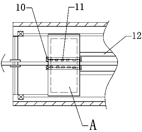
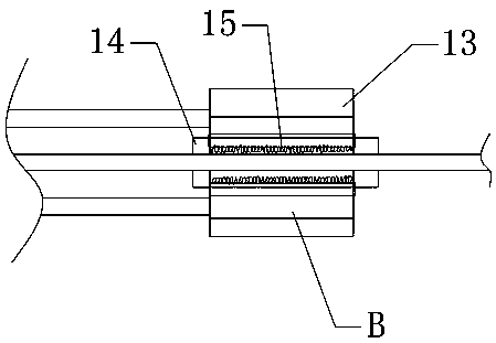
[0026] The embodiment is basically as attached figure 1 , figure 2 Shown: the galvanizing device for the electrode wire core material for precision mold cutting, including a frame 1 and a galvanizing mechanism 2 arranged on the frame, and the galvanizing mechanism 2 includes a cabinet 3 arranged on the frame 1, and The horizontal pipe 4 in the cabinet 3 is provided with guide grooves 5 on the upper and lower pipe walls of the horizontal pipe 4, and the inner sides of the upper and lower pipe walls of the horizontal pipe 4 are provided with cavities communicating with the guide grooves 5 6. The horizontal pipeline 4 is provided with a liquid zinc guide pipe 7 connected to the cavity 6, and a vertical pole 8 is slidably connected to the guide groove 5, and the pole 8 is provided with a cavity on the inner side of the pipe wall. 6 connected inner cavities, and the middle part of the column rod 8 is provided with a round hole 10 to accommodate the passage of the electrode wire c...

Embodiment 2

[0031] Such as Figure 5 As shown, the structure and principle of this embodiment are basically the same as those of Embodiment 1, the difference being that: the left and right ends of the pole 8 are provided with guide strips 20, and the guide strips 20 can cover the upper and lower sides of the horizontal pipe 4. The guide groove 5 on the lower pipe wall, the guide strips 20 at both ends of the mast 8 all stretch out from the outsides of the both side baffle plates of the horizontal pipe 4, and the guide groove 5 can be shielded by setting the left and right ends of the mast 8. Bar 20, to ensure that during the process of moving the galvanized pole 8, too much zinc liquid will not overflow in the guide groove 5, saving materials, and when the pole 8 moves from one end to the other, it will protrude from the horizontal through sliding The guide bar 20 on the outside of the baffle plate at both ends of the pipeline 4 can reset the mast 8 and the support 12 connected thereto, s...


PUM


Abstract

The invention discloses a galvanizing device of an electrode wire core material for precise mold cutting. The galvanizing device of the electrode wire core material for precise mold cutting comprises a machine frame and a galvanizing mechanism arranged on the machine frame. The galvanizing mechanism comprises a machine box arranged on the machine frame. The upper pipe wall and the lower pipe wall of a horizontal pipeline are both provided with guide grooves. The inner sides of the upper pipe wall and the lower pipe wall of the horizontal pipeline are both provided with cavities communicating with the guide grooves. The horizontal pipeline is provided with a zinc flow guide pipe communicating with the cavities. A vertical pole is connected with the guide grooves in a sliding manner. The inner wall of a round hole is provided with liquid outlets communicating with the inner cavity. The middle portion of a chuck is provided with a pipe opening coaxial with the round hole. The pipe opening is provided with brush bristles which can make contact with the electrode wire core material. The middle portions of baffles are both provided with round openings allowing the electrode wire core material to penetrate. One end, close to the chuck, of the baffle is provided with an air blower. One end, close to the pole, of the baffle is provided with a rolling machine. The galvanizing device of the electrode wire core material for precise mold cutting solves the problems that in an existing galvanizing pot galvanizing technology, galvanization is uneven, and the core material is prone to thermal deformation and difficult to collect.

Description

technical field [0001] The invention relates to the technical field of process production of electrode wire for electrical discharge machining of electric wires, in particular to a galvanizing process and production equipment for electrode wire core materials used for cutting precision molds. Background technique [0002] Machining technology is changing with each passing day. As a special precision machining technology, wire-cut EDM has developed rapidly, especially the slow-moving wire-cut wire-cut machining in wire-cut EDM. The development of wire cutting technology is inseparable from the simultaneous development of wire electrode technology. Now the design concept of slow wire machine tool popular in the world is designed according to the performance of electrode wire. [0003] Due to the complexity of the structure of the mold itself and the high requirements on the precision parameters of the surface of the mold after cutting, the cutting of precision molds is usually...

Claims


Application Information

Patent Timeline
Patent Type & Authority Patents(China)
IPC IPC(8): C25D7/06C25D5/08
CPCC25D5/08C25D7/0607
Inventor 吕献平
Owner 重庆鑫盟精密模具有限公司
Learn More