Measuring device of pouring pile concrete surface

A technology of concrete surface and cast-in-place piles, which is applied in construction, foundation structure tests, foundation structure engineering, etc., can solve the problems of large access, increased mud weight, waste, etc., to achieve scientific and reasonable structure, control material waste, and safe use convenient effect

Inactive Publication Date: 2017-12-26
中地君豪高科股份有限公司
View PDF5 Cites 4 Cited by
  • Summary
  • Abstract
  • Description
  • Claims
  • Application Information

AI Technical Summary

Problems solved by technology

[0002] The traditional concrete surface measurement device is mainly composed of a measuring rope and a short steel bar or a heavy steel product. The advantage of this device is that it is easy to make and the materials are easy to obtain. However, this device completely relies on experience to measure the depth of the concrete surface. , the error is large, and the depth of the concrete surface cannot be accurately measured
Especially when the concrete surface is deep from the ground when the pouring is stopped, due to the increased mud weight and the instability of the upper borehole wall, the measured concrete top surface is quite different from the actual concrete surface. In order to ensure that the pile top concrete Quality, in actual construction, more concrete is often poured, the construction time is longer, and a large amount of unnecessary construction cost increase or waste is caused

Method used


Image

  • Measuring device of pouring pile concrete surface
  • Measuring device of pouring pile concrete surface
  • Measuring device of pouring pile concrete surface

Examples


Embodiment

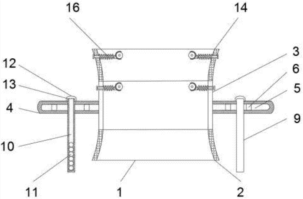
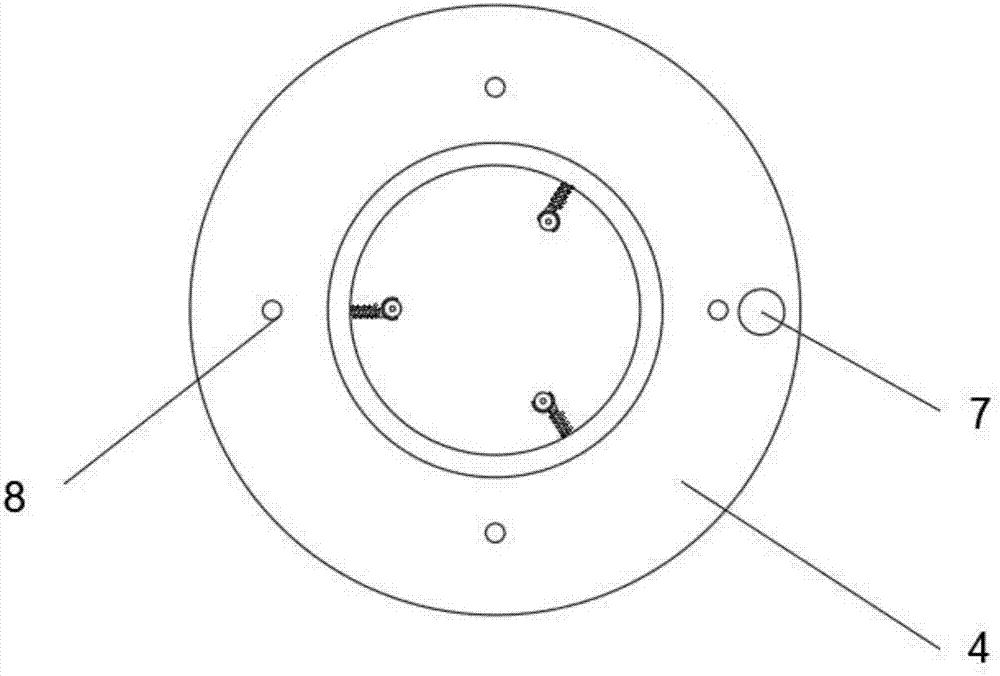
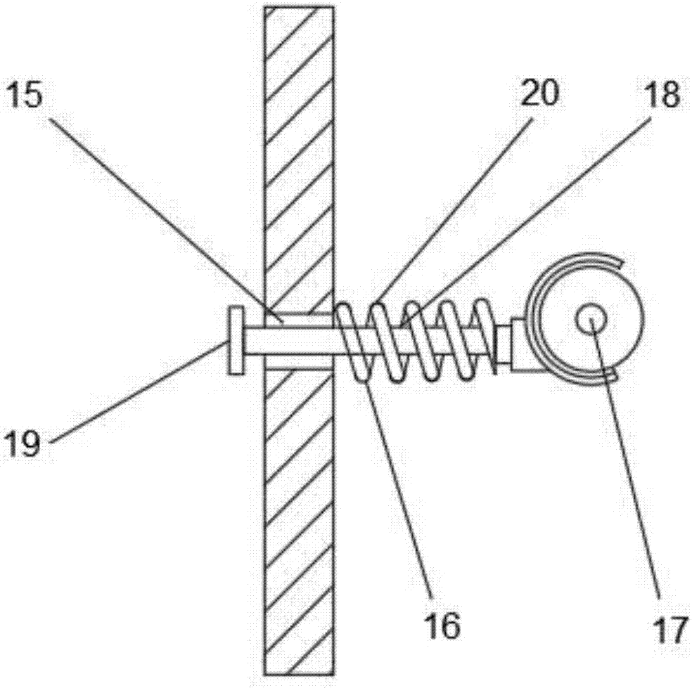
[0021] Example: such as Figure 1-5 As shown, the present invention provides a technical solution, a concrete surface measuring device for cast-in-situ piles, including a measuring device body 1, a lower sleeve 2, a middle sleeve 3, a floating plate 4, a cavity 5, a column 6, a measuring device Rope hole 7, first through hole 8, metal rod 9, blind hole 10, shot ball 11, end cap 12, threaded hole 13, upper sleeve 14, second through hole 15, guide 16, universal wheel 17, connecting Rod 18, baffle plate 19, spring 20, conduit 21, measuring rope 22, tension sensor 23, runner 24, motor 25, base 26, telescopic rod 27, directional wheel 28, battery 29 and TD-CLF-L3 type controller 30. The lower part of the measuring instrument body 1 is provided with a lower sleeve 2, the top surface of the lower sleeve 2 is provided with a middle sleeve 3, the outer side of the middle sleeve 3 is sleeved with a floating plate 4, and the inside of the floating plate 4 is provided with a cavity 5, A ...


PUM


Abstract

The invention discloses a measuring device of pouring pile concrete surface, which comprises a measuring device body, a middle sleeve, a floating board, a guider, a measuring rope, a tension sensor, a battery, and a TD-CLF-L3 type controller. The outer side of the middle sleeve is sleeved with the floating board, a metal rod is arranged inside a first through hole, a lead ball is arranged inside a blind hole, the guider is arranged inside a second through hole, the measuring device body is sheathed in the middle of a guide tube, the tension sensor is arranged on one side of the measuring rope, near the floating board, a motor is arranged on one side of a runner, a telescopic rod is arranged on one side of the top of a base, and the TD-CLF-L3 type controller is arranged on one side of the battery. The device, when used for pouring concrete, moves upwards along with the concrete surface so that the depth of the concrete surface can be accurately known through the measuring rope connected with the device. Even in the event of an upper borehole collapse, the measurement will not be affected and material waste can be effectively controlled. The measuring rope is pulled by the motor, thereby saving manpower.

Description

technical field [0001] The invention relates to the technical field of concrete pouring measurement, in particular to a measuring device for the concrete surface of cast-in-situ piles. Background technique [0002] The traditional concrete surface measurement device is mainly composed of a measuring rope and a short steel bar or a heavy steel product. The advantage of this device is that it is easy to make and the materials are easy to obtain. However, this device completely relies on experience to measure the depth of the concrete surface. , the error is very large, and the depth of the concrete surface cannot be accurately measured. Especially when the concrete surface is deep from the ground when the pouring is stopped, due to the increased mud weight and the instability of the upper borehole wall, the measured concrete top surface is quite different from the actual concrete surface. In order to ensure that the pile top concrete Quality, in actual construction, more conc...

Claims


Application Information

Patent Timeline
Patent Type & Authority Applications(China)
IPC IPC(8): E02D33/00
CPCE02D33/00
Inventor 李军郭利生宋明智沈远志周余鹏刘凤丽
Owner 中地君豪高科股份有限公司
Why Eureka
Try Eureka