SAGD horizontal well concentric pipe steam injection heat transfer method
A technology of concentric tubes and horizontal wells, which is applied in the field of steam injection and heat transfer in SAGD horizontal wells with concentric tubes, to achieve the effect of optimizing development effect and improving development effect.
Active Publication Date: 2017-12-26
PETROCHINA CO LTD
10 Cites 2 Cited by
AI-Extracted Technical Summary
Problems solved by technology
[0006] The current oilfield SAGD using concentric tube steam injection has just entered the experimental stage, and the analytical model for the concentric tube preheating cycle has not yet been established, and there are no related articles in China. It is necessary to calculate and ...
Abstract
The invention provides an SAGD horizontal well concentric pipe steam injection heat transfer calculation method. An SAGD horizontal well concentric pipe comprises a long pipe, a short pipe, a screen pipe and a sleeve which are concentrically arranged; the long pipe comprises a vertical section and a horizontal section connected with the vertical section; the vertical section is sleeved with the short sleeve, and the short pipe and the long pipe are arranged in a spaced mode; the short pipe is sleeved with the sleeve, and the sleeve and the short pipe are arranged in a spaced mode; and the screen pipe is connected to the end of the sleeve and arranged on the periphery of the horizontal section in a sleeving mode, and the screen pipe and the horizontal section are arranged in a spaced mode. The SAGD horizontal well concentric pipe steam injection heat transfer method comprises the steps that S1, the heat loss in the portion, at the vertical section, of the long pipe and the heat loss in the short pipe are determined; and S2, the heat loss in the portion, at the horizontal section, of the long pipe and the heat loss of the screen pipe are determined. According to the SAGD horizontal well concentric pipe steam injection heat transfer method, the heat transfer loss of steam injected from the vertical section of the long pipe can be determined, and the basis is provided for optimization of the SAGD horizontal well circulating preheating technique and improvement of the development effect.
Application Domain
InsulationFluid removal
Technology Topic
Vertical segmentEngineering +3
Image
Examples
- Experimental program(1)
Example Embodiment
[0039] It should be noted that the embodiments in the application and the features in the embodiments can be combined with each other if there is no conflict. Hereinafter, the present invention will be described in detail with reference to the drawings and in conjunction with the embodiments.
[0040] It should be noted that the terms used here are only for describing specific implementations, and are not intended to limit the exemplary implementations according to the present application. As used herein, unless the context clearly indicates otherwise, the singular form is also intended to include the plural form. In addition, it should also be understood that when the terms "comprising" and/or "including" are used in this specification, they indicate There are features, steps, operations, devices, components, and/or combinations thereof.
[0041] It should be noted that the terms "first" and "second" in the description and claims of the application and the above-mentioned drawings are used to distinguish similar objects, and are not necessarily used to describe a specific sequence or sequence. It should be understood that the data used in this way can be interchanged under appropriate circumstances, so that the embodiments of the present application described herein can be implemented in a sequence other than those illustrated or described herein, for example. In addition, the terms "including" and "having" and any variations of them are intended to cover non-exclusive inclusions. For example, a process, method, system, product, or device that includes a series of steps or units is not necessarily limited to the clearly listed Those steps or units may include other steps or units that are not clearly listed or are inherent to these processes, methods, products, or equipment.
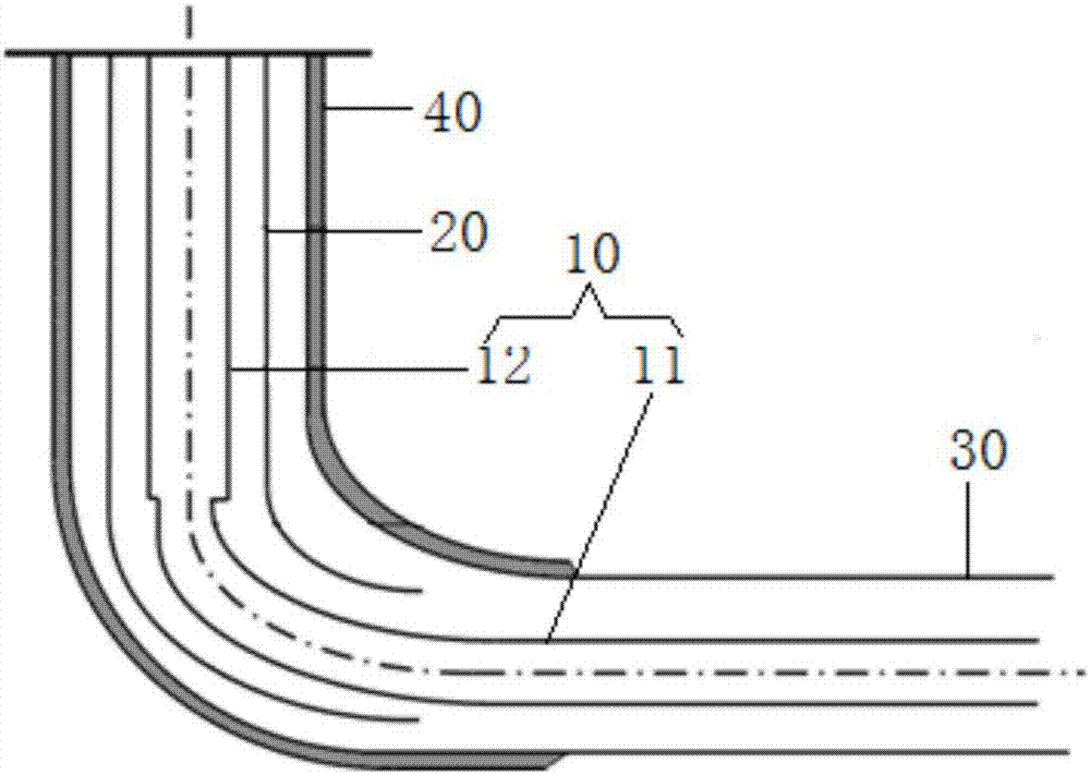
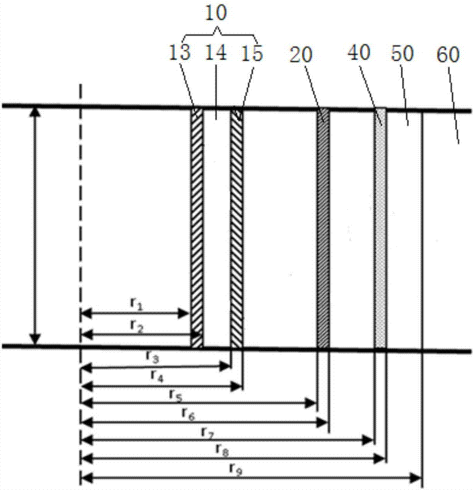
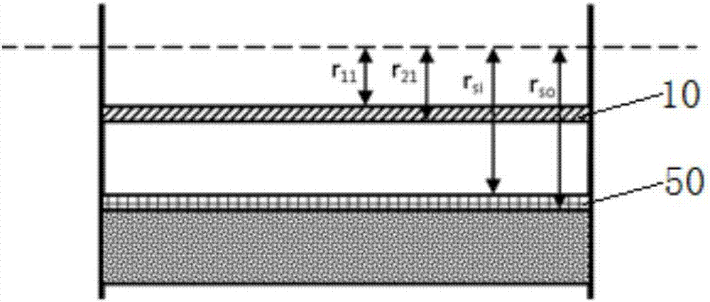
[0042] See Figure 1 to Figure 3 As shown, according to an embodiment of the present invention, a method for calculating the heat transfer of concentric pipe steam injection in a SAGD horizontal well is provided.
[0043] Combine figure 1 As shown, the SAGD horizontal well concentric pipe in this embodiment includes a long pipe 10, a short pipe 20, a screen 30, and a casing 40 that are concentrically arranged. The long pipe 10 includes a vertical section 11 and a vertical section 11 connected to it. Horizontal section 12; short pipe 20 is sleeved on the outer circumference of vertical section 11 and spaced apart from long pipe 10; sleeve 40 is sleeved on the outer circumference of short pipe 20 and spaced apart from short pipe 20; screen 30 is connected to sleeve 40 The ends of the sieve tube are sleeved on the outer circumference of the horizontal section 12, and the screen 30 and the horizontal section 12 are spaced apart.
[0044] Such as figure 2 As shown, the long tube 10 in this embodiment includes an inner tube sleeve 13, an outer tube sleeve 15 and a heat insulation layer 14 provided between the inner tube sleeve 13 and the outer tube sleeve 15.
[0045] During operation, the outer periphery of the concentric pipe of the SAGD horizontal well in this implementation is filled with a cement ring 50, and the outer periphery of the cement ring 50 is a stratum 60. During the preheating cycle, steam is injected from the vertical section 11 of the long pipe 10, exits from the toe end of the SAGD horizontal well, exchanges heat with the oil layer in the screen 30 at the horizontal section 12, and then returns to the SAGD from the short pipe 20 Horizontal well.
[0046] Specifically, the SAGD horizontal well concentric tube steam injection heat transfer method in this embodiment includes step S1 and step S2.
[0047] Among them, the purpose of step S1 is to determine the heat loss in the long tube 10 at the vertical section 11 and the heat loss in the short tube 20; the purpose of step S2 is to determine the heat loss and the screen tube in the long tube 10 at the horizontal section 12 30 heat loss. According to the concentric tube steam injection heat transfer method of SAGD horizontal well in this embodiment, the heat transfer loss of steam injected from the vertical section 11 of the long tube 10 can be determined, which provides a basis for optimizing the SAGD horizontal well cycle preheating process and improving the development effect.
[0048] The following describes the SAGD horizontal well concentric tube steam injection heat transfer method in this embodiment:
[0049] Between calculations, it is assumed that no steam flows into the oil layer during the preheating cycle, and the oil layer is heated by heat conduction.
[0050] During the steam injection cycle, the high-temperature steam in the concentric pipes of the SAGD horizontal well has heat and spontaneously transfers to the formation 60. Heat is transferred through 9 links: forced convection heat transfer with phase change between the steam injected into the long tube 10 and the inner wall of the inner tube sleeve 13, the heat conduction of the inner tube sleeve 13, the heat conduction of the heat insulation layer 14, and the outer tube sleeve 15 heat conduction, the convective heat exchange between the fluid in the gap between the outer wall of the long tube 10 and the short tube 20 and the outer wall of the long tube 10, the heat conduction of the tube wall of the short tube 20, the outer wall of the short tube 20 and the inner wall of the sleeve 40 The convective heat exchange between the fluid in the gap and the outer wall of the short tube 20, the heat conduction of the pipe wall of the casing 40, and the heat conduction of the cement ring 50 are connected in series to form the heat transfer "in the wellbore".
[0051] Combine figure 2 As shown, according to the above-mentioned link that affects heat transfer, it can be obtained that the heat transfer method of concentric tube steam injection in SAGD horizontal well is as follows:
[0052] Take a small section of dz along the length of the long tube 10 in the vertical section 11 for analysis, see figure 2.
[0053] (1) Determine the heat loss A in the long pipe 10 at the vertical section 11
[0054]
[0055] Where: d 1 Is the inner diameter of the long pipe, in m;
[0056] T 1 Is the steam temperature in the long tube, the unit is ℃;
[0057] T 2 Is the steam temperature in the short tube, in ℃;
[0058] K 1 Is the heat transfer coefficient between the long tube and the short tube, W/(m 2 ·°C).
[0059] The solution process of K1 is as follows:
[0060] 1) There is a forced convection heat exchange phenomenon accompanied by phase change between the steam injected into the long pipe 10 and the inner wall of the inner pipe sleeve 13, and the heat flow rate is q 1 , The calorie formula is:
[0061]
[0062] Where: h 1 Is the face-to-flow heat transfer coefficient of the steam in the long tube 10 to the inner wall of the long tube 10, in W/(m 2 ·℃);
[0063] T 1 Is the steam temperature in the long tube 10, in ℃;
[0064] T c1 Is the temperature of the inner wall of the long tube 10, in ℃;
[0065] d 1 Is the inner diameter of the long tube 10, the unit is m; A 1 Is the area of the inner wall of the long pipe 10 in m 2;
[0066] l is the length of the vertical section of the long pipe 10, in m.
[0067] 2) The inner wall of the inner pipe sleeve 13 transfers heat to the outer wall of the inner pipe sleeve 13 through heat conduction, and the heat flow is set to q 2 , From the heat conduction rate equation of the single-layer cylindrical wall:
[0068]
[0069] Where: λ tb Is the thermal conductivity of the inner sleeve 13 in W/(m·℃);
[0070] T c2 Is the temperature of the outer wall of the inner sleeve 13 in ℃;
[0071] d 2 It is the outer diameter of the inner tube sleeve 13, and the unit is m.
[0072] 3) The thermal insulation effect of the thermal insulation layer 14 is mainly considered when the heat propagates in the thermal insulation layer 14. The thermal process in the thermal insulation layer 14 includes three methods of heat conduction, convection and radiation. The SY/T5324-94 (prestressed thermal insulation oil pipe) standard puts forward the concept of "apparent thermal conductivity", which regards the heat transferred in the thermal insulation layer 14 of the long tube 10 in the three ways of heat conduction, convection and radiation as thermal insulation. A kind of "hypothetical solid" with the same thickness transfers heat in a purely thermally conductive manner. The thermal conductivity of this "hypothetical solid" is called "apparent thermal conductivity", and the heat flow is q 3 , The heat transfer process is regarded as the heat conduction process:
[0073]
[0074] Where: λ in Is the apparent thermal conductivity of the long tube 10 at the vertical section 11, in W/(m·℃);
[0075] T c3 Is the temperature of the inner wall of the outer sleeve 15 in ℃;
[0076] Is the inner diameter of the outer sleeve 15 in m.
[0077] 4) The inner wall of the outer sleeve 15 transfers heat to the outer wall of the outer sleeve 15 through heat conduction, and the heat flow is set to q 4 :
[0078]
[0079] Where: T c4 Is the temperature of the outer wall of the outer sleeve 15 in ℃;
[0080] d 4 It is the outer diameter of the outer sleeve 15 and the unit is m.
[0081] 5) In the short tube 20, the heat is mainly transferred through convection between the return fluid and the outer wall of the long tube 10, and the heat flow rate is q 5 :
[0082]
[0083] Where: T 2 Is the fluid temperature in the short tube 20, ℃;
[0084] h 2 Is the face-to-flow heat transfer coefficient of the fluid in the short tube 20 to the outer wall of the vertical section 11 of the long tube 10, in W/(m 2 ·℃);
[0085] When the heat transfer is stable, the continuity of heat transfer shows: q 1 =q 2 =q 3 =q 4 =q 5
[0086] Definition Φ 1 =q 1 =q 2 =q 3 =q 4 =q 5
[0087] You can get:
[0088]
[0089] Define the total heat transfer coefficient between the long tube 10 and the short tube 20 as:
[0090]
[0091] At the same time, because in the actual heat transfer process, the influence of fouling must be considered, so the actual heat transfer process needs to consider the influence of the heat transfer and thermal resistance due to the presence of fouling in the above heat transfer process, namely:
[0092]
[0093]
[0094] Through the above analysis, the heat transfer coefficient between the long tube 10 and the short tube 20 can be obtained as:
[0095]
[0096] Among the parameters to be calculated, the heat transfer coefficient h of the steam in the long tube 10 to the inner wall of the long tube 10 is 1 , The convective heat transfer coefficient of the fluid in the short tube 20 needs to be solved by the convective heat transfer theory in heat transfer. The solution theory is as follows:
[0097] Before discussing, define a few dimensionless numbers:
[0098] Reynolds number: Where ρ is the density of the fluid, u is the flow rate, d is the inner diameter of the tube, and η is the viscosity. Describe the flow state of the fluid (laminar flow, transition zone, turbulent flow), in general, for the flow in the pipe, Re =10000, turbulent flow.
[0099] Nusselt number: Among them, h is the convective heat transfer coefficient (quantity to be determined), d pipe diameter, and the thermal conductivity of lambda fluid; it describes the amount of convective heat transfer strength.
[0100] Prandtl number: η viscosity, thermal conductivity of λ fluid, c p Fluid specific heat capacity; describes the size of fluid momentum transfer capacity and heat transfer capacity.
[0101] The relationship between three dimensionless numbers:
[0102] Nu=f(Re,Pr)
[0103] It can be seen that the required convective heat transfer coefficient h, as long as the Nusselt number Nu can be obtained, and because Nu=f(Re,Pr), the Reynolds number Re and Prandtl number Pr are required first , Reynolds number Re can be calculated according to the flow rate of the fluid in the pipe, and then combined with the physical parameters of the fluid to be calculated; Prandtl number Pr can be calculated directly from the physical parameters of the fluid; after calculating these two quantities, you can get Nusselt number Nu. Thus, the convective heat transfer coefficient h is obtained.
[0104] Reynolds number Re
[0105]
[0106] Prandtl Number Pr
[0107]
[0108] Nusselt number Nu
[0109] a. Laminar flow time (Re
[0110]
[0111] b. Transition zone (2300
[0112]
[0113] f=(1.82log Re-1.64) -2
[0114] c. Turbulence (Re> =10000), using the Peter-Hoff formula:
[0115]
[0116] f=(1.82log Re-1.64) -2
[0117] Convection heat transfer coefficient h
[0118]
[0119] (2) Determine the heat loss B of the screen 30 at the horizontal section 12
[0120] Use the following formula to determine the heat loss B in the short tube 20:
[0121]
[0122] Where: T h Is the temperature of the outer edge of the cement ring 50 in ℃;
[0123] K 2 Is the total heat transfer coefficient between the short tube 20 and the formation 60, the unit is W/(m 2 ·°C).
[0124] Where K 2 The solution process for is as follows:
[0125] 1) Convection heat exchange occurs between the fluid in the short tube 20 and the inner wall of the short tube 20, and the heat flow rate is q:
[0126]
[0127] Where: T d1 The temperature of the inner wall of the short tube 20, in ℃;
[0128] d 5 Is the inner diameter of the short tube 20, the unit is m;
[0129] h 3 Is the convective heat transfer coefficient of steam in the short tube 20 to the inner wall of the short tube 20, the unit is W/(m 2 ·°C).
[0130] 2) The inner tube wall of the short tube 20 transfers heat to the outer tube wall through heat conduction, and the heat flow is set as q:
[0131]
[0132] Where: λ stb Is the thermal conductivity of the wall of the short tube 20, in W/(m·℃);
[0133] T d2 Is the temperature of the outer wall of the short tube 20 in ℃;
[0134] d 6 It is the outer diameter of the short tube 20, and the unit is m.
[0135] 3) Heat transfer in the casing 40 through natural convection and radiation, set the heat flow as q:
[0136]
[0137] Where: h c3 Is the convective heat transfer coefficient in the casing 40, the unit is W/(m 2 ·℃);
[0138] h r3 Is the heat radiation heat transfer coefficient in the casing 40, the unit is W/(m 2 ·℃);
[0139] T 3 Is the temperature of the inner wall of the casing 40, in ℃;
[0140] d 7 It is the inner diameter of the casing 40 and the unit is m.
[0141] 4) There is heat conduction between the outer wall of the casing 40 and the cement ring 50, and the heat flow is set as q:
[0142]
[0143] Where: λ ct Is the thermal conductivity of the casing 40, the unit is W/(m·℃);
[0144] λ sn The thermal conductivity of the cement ring is 50, the unit is W/(m·℃);
[0145] d 8 Is the outer diameter of casing 40, in m;
[0146] d 9 Is the outer diameter of the cement ring 5, in m.
[0147] 5) The heat transfer between the cement ring 50 and the ground 60
[0148] Since it is unstable heat conduction, it changes with time. The heat loss to the formation 60 begins to increase, but as the steam injection progresses, the temperature of the formation 60 increases, and the heat transfer dynamic temperature difference ΔT will decrease, resulting in a decrease in heat loss. Suppose the heat flow is q, which can be expressed as:
[0149] q=πd 8 λ d (T h -T 4 )/f(t)
[0150] Where: λ d Is the thermal conductivity of the formation 60, the unit is W/(m·℃);
[0151] T h Is the temperature of the outer edge of the cement ring 50 in ℃;
[0152] T 4 Is the temperature at the junction of cement ring 50 and stratum 60, in ℃;
[0153] f(t) is a dimensionless time function.
[0154] According to Ramey H J's "Wellbore Heat Transmission" published on JPT in 1962:
[0155]
[0156] Where: α d Is the thermal diffusivity of the formation 60, the unit is m 2 /s;
[0157] t is time and the unit is s.
[0158] According to the definition of thermal diffusivity:
[0159]
[0160] In the formula: λ is the thermal conductivity of the rock in W/(m·K);
[0161] ρ is the equivalent density of the rock in kg/m 3;
[0162] C P It is the specific heat capacity of the rock in the formation 60, in J/kg·K.
[0163] Considering the continuity of heat transfer, it can be seen that the heat lost to the annulus by the short tube is equal to the heat lost from the annulus to the outer edge of the cement ring 50, and we get:
[0164]
[0165] Solving for K2 is: (Considering the fouling thermal resistance r5)
[0166]
[0167] Considering the continuity of heat transfer, it can be known that the amount of heat lost to the outer edge of the cement ring 50 is equal to the amount of heat transferred from the outer edge of the cement ring 50 to the formation, and we obtain:
[0168]
[0169] The temperature expression of the outer edge of the cement ring 50 can be obtained as:
[0170]
[0171] In step S1, the heat loss in the long pipe 10 at the horizontal section 12 is determined as follows:
[0172] Take a small section of dz in the horizontal section 12 along the length of the long tube 10 for analysis, see image 3.
[0173] The horizontal section 12 has only one smooth oil pipe, and the heat is transferred from the long pipe 10 to the annulus of the screen 30, and then to the oil layer through the annulus of the screen 30.
[0174] (3) Determine the heat loss in the long tube 10 at the horizontal section 12
[0175]
[0176] Where: K 11 Is the heat transfer coefficient between the long tube 10 and the inner wall of the screen 30, in W/(m 2 ·℃);
[0177] d 11 The inner diameter of the long pipe 10 at the 12 horizontal section, in m;
[0178] T s It is the temperature in the annulus of the horizontal section of the screen, in ℃.
[0179] T 11 Is the steam temperature in the horizontal section of the long pipe, in ℃;
[0180] The heat lost in the long tube 10 to the inner wall of the screen 30 is Φ 1 (Consider dirt thermal resistance):
[0181]
[0182] Where: h 11 Is the heat transfer coefficient of the steam in the long tube 10 to the inner wall of the long tube 10, the unit is W/(m 2 ·℃);
[0183] h 21 Is the heat transfer coefficient of the steam between the outer wall of the screen 30 and the inner wall of the screen 30 to the outer wall of the long tube 10, in W/(m 2 ·℃);
[0184] d 11 Is the inner diameter of the long pipe 10 at the 12 horizontal section, the unit is m;
[0185] T s Is the temperature of the screen 30 at the horizontal section 12, in ℃;
[0186] T 11 It is the steam temperature in the horizontal section 12 long pipe 10, and the unit is °C.
[0187] The heat transfer coefficient between the long tube 10 of the horizontal section 12 and the inner wall of the screen tube 30 is:
[0188]
[0189] Where: r 11 Is the inner wall radius of the long pipe 10 at the horizontal section 12, the unit is m;
[0190] r 21 Is the radius of the outer wall of the long tube 10 at the horizontal section 12, in m;
[0191] λ tb1 Is the thermal conductivity of the long tube 10 at the horizontal section 12, in W/(m·℃).
[0192] (4) Calculation of heat loss of screen 30 at horizontal section 12
[0193] The horizontal section 12 dissipates heat to the outer oil layer, and the temperature distribution in the oil layer during the heat dissipation process can refer to the document "Thermal Transient Analysis Applied to Horizontal Wells" (SPE/PS/CHOA 117435PS2008-320):
[0194]
[0195] among them: T x Is the temperature of a certain point in the oil layer, the unit is ℃;
[0196] T s Is the temperature inside the sieve 30, the unit is ℃;
[0197] λ e Is the thermal conductivity of the oil layer, W/(m·K);
[0198] r s Is the radius of the inner wall of the screen 30, in m;
[0199] α is the thermal diffusion coefficient of the oil layer, the unit is m 2 /s;
[0200] λ is the time of 1 day, the unit is s;
[0201] t is the number of days of heating, and the unit is d.
[0202] Thus, the heat flux density of heat dissipation can be obtained as:
[0203]
[0204] among them: The series expansion can be expressed as:
[0205]
[0206] When the steam injection time is longer (satisfying γ/t <0.01), when the steam injection temperature is constant:
[0207]
[0208] It is known that the steam temperature in the screen 30 is T s , The heat dissipation of the screen 30 to the horizontal section 12 can be obtained as:
[0209]
[0210] Since the oil layer outside the horizontal section of a horizontal well is a mixture of rock, oil, water, etc., according to the document "Thermal Conductivity Estimation From Temperature Logs" (SPE 21542), the thermal conductivity of the oil layer is λ e It can be calculated by the following formula:
[0211]
[0212] Among them, a, b, c, d, e are coefficients, S w Is the water saturation (decimal), S o Is oil saturation (decimal), φ is oil reservoir porosity (decimal), and T is temperature (℃). The document also provides a set of coefficient values obtained through multiple regression: a=4.318, b=4.883, c=0.474, d=0.987, e=0.002.
[0213] In the actual calculation, the porosity is 0.25, the oil saturation is 0.7, and the water saturation is 0.3. The calculated thermal conductivity of the oil layer is 2.5w/(m.K).
[0214] The above are only preferred embodiments of the present invention and are not used to limit the present invention. For those skilled in the art, the present invention can have various modifications and changes. Any modification, equivalent replacement, improvement, etc., made within the spirit and principle of the present invention shall be included in the protection scope of the present invention.
PUM


Description & Claims & Application Information
We can also present the details of the Description, Claims and Application information to help users get a comprehensive understanding of the technical details of the patent, such as background art, summary of invention, brief description of drawings, description of embodiments, and other original content. On the other hand, users can also determine the specific scope of protection of the technology through the list of claims; as well as understand the changes in the life cycle of the technology with the presentation of the patent timeline. Login to view more.
Similar technology patents
Classification and recommendation of technical efficacy words
- Improve development performance