Intelligent gas stove burner

A gas stove and burner technology, which is applied to burners, gas fuel burners, combustion methods, etc., can solve problems such as shortening of the flame of the kindling head, easy extinguishing of the flame of the kindling head, insufficient kindling head to ensure the ignition of the flame of the burner head, etc.

Pending Publication Date: 2017-12-26
HUBEI JINYUAN HOTEL EQUIP SUPPLIES
View PDF0 Cites 0 Cited by
  • Summary
  • Abstract
  • Description
  • Claims
  • Application Information

AI Technical Summary

Problems solved by technology

[0003] The problem is that the gas supply pipeline of the ignition head is connected with the gas supply pipeline of the burner head. When the pipeline of the burner head is not connected, the gas of the ignition head has enough pressure to make the flame of the ignition head have a sufficient length. When the pipeline of the burner head is connected, due to the diversion of gas, the gas pressure of the ignition head will drop, and the flame of the ignition head will shorten.
And the flame of the tinder head is also easy to extinguish
There is currently no better way to overcome this technical problem

Method used


Image

  • Intelligent gas stove burner
  • Intelligent gas stove burner
  • Intelligent gas stove burner

Examples


Embodiment 1

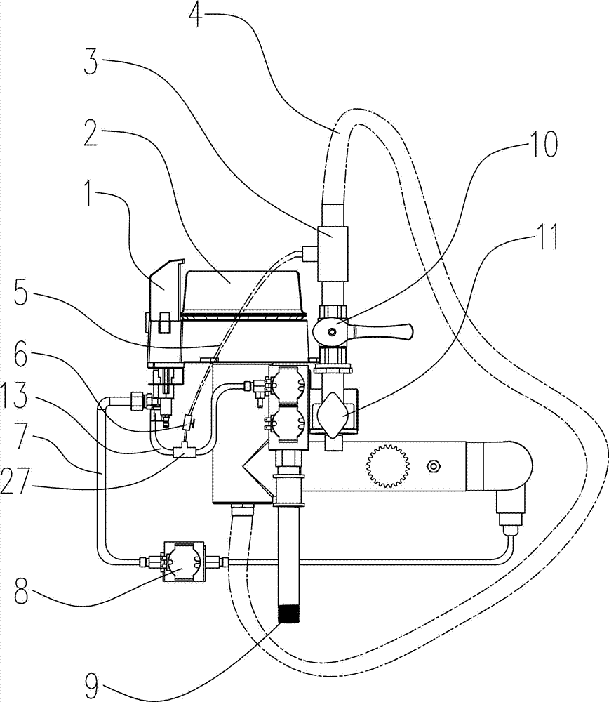
[0028] Such as Figure 1~3 , 6, an intelligent gas stove burner, including a burner 2, a fire head 1 is provided on one side of the burner 2, the burner 2 is connected to the gas proportional valve 11 through a gas pipe 4, and the fire head 1 passes through the fire pipe 13 is connected with the gas proportional valve 11, the gas pipe 4 is provided with a gas tee 3, the gas tee 3 is connected with one end of the fire balance pipe 5, and the other end of the fire balance pipe 5 is connected with the fire pipe 13 through the fire pipe tee. With this structure, when igniting, the gas proportional valve 11 first connects the ignition head 1, the main control chip 12 drives the electrode discharge of the ignition module 24, ignites the ignition head 1, and then the burner 2 supplies gas, and the flame of the ignition head 1 Fire burner 2. Due to the existence of the ignition balance pipe 5, when the burner head 2 starts to supply gas, part of the gas enters the ignition head 1 fro...

Embodiment 2

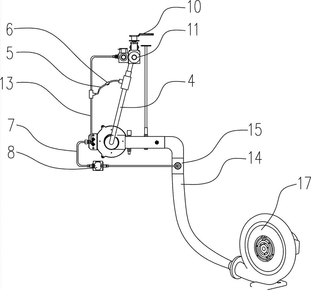
[0035] On the basis of Embodiment 1, in a preferred solution, an air duct 14 is also provided, and one end of the air duct 14 is connected with the fan 17, and the other end of the air duct 14 is connected with the burner 2, and the air duct 14 is also provided with an air duct. Pipe tee 15, the air duct tee 15 is connected with the kindling kinder air supply pipe 7, and the kindling kinder kindling supplementary air pipe 7 is connected with the kindling kind head 1.

[0036] The preferred solution is as figure 1 Among them, the kindling air supply pipe 7 is provided with a kindling supply air valve 8, and the kindling supply air valve 8 is a manual flow regulating valve; in this example, a manual flow regulating valve is preferably used. to reduce the difficulty of control.

[0037] Alternatively, the ignition supplementary air valve 8 is an electronically controlled proportional valve, and the ignition supplementation air valve 8 is electrically connected to the main contro...

Embodiment 3

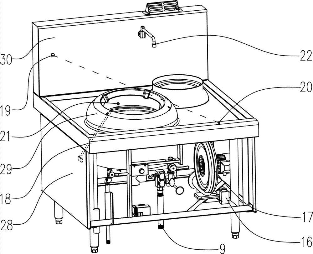
[0042]On the basis of Examples 1 and 2, the preferred scheme is as figure 2 Among them, also be provided with pot pressure detector 18, pot pressure detector 18 is arranged on the position of pot platform 29, pot pressure detector 18 is electrically connected with main control chip 12, and main control chip 12 is electrically connected with ignition module 24. With this structure, the position of the pot can be detected by the pot pressure detector 18, so that the flame of the burner 2 can be intelligently controlled. And save energy consumption, reduce the risk of operation.

[0043] The preferred solution is as Figure 7 In the above-mentioned pot pressure detector 18, the detection rod 181 is installed in the detection slide seat 182 in a movable manner, and the end part of the detection rod 181 protrudes out of the pot platform 29, and a limit block is arranged on the detection rod 181 183, a spring 184 is provided between the limit block 183 and the detection slide 182...


PUM


Abstract

The invention provides an intelligent gas stove burner. The intelligent gas stove burner comprises a burner; a kindling head is arranged on one side of the burner; the burner is connected with a gas proportional valve through a gas pipe; the kindling head is connected with the gas proportional valve through a kindling pipe; a gas tee joint is arranged on the gas pipe, and is connected with one end of a kindling balance pipe; and the other end of the kindling balance pipe is connected with the kindling pipe through a kindling pipe tee joint. The kindling balance pipe is adopted; after gas is introduced in the burner, the gas of the burner is partially leaded to the kindling head to guarantee no pressure change of the gas; flame of the kindling head has enough length; and when the flame of the burner is extinguished, the burner can be ignited again by the kindling head. The intelligent gas stove burner adopts the scheme of controlling through a main control chip to intelligently control the gas of the burner, the gas of the kindling head and the kindling air supply.

Description

technical field [0001] The invention relates to the field of gas stoves, in particular to an intelligent gas stove burner. Background technique [0002] In existing commercial gas stoves, a kindling head is all provided. When in use, after opening the gas valve, first utilize the electrode needle in the ignition module (24) to ignite the kindling head, and then use the kindling head to ignite the stove head. [0003] The problem is that the gas supply pipeline of the ignition head is connected with the gas supply pipeline of the burner head. When the pipeline of the burner head is not connected, the gas of the ignition head has enough pressure to make the flame of the ignition head have a sufficient length. When the pipeline of the burner head is connected, due to the diversion of gas, the gas pressure of the ignition head will drop, and the flame of the ignition head will shorten. . And the flame of the tinder head is also easy to extinguish. There is no better method to...

Claims


Application Information

Patent Timeline
IPC IPC(8): F23D14/02F23D14/46F23D14/60F24C3/12
CPCF23D14/02F23D14/46F23D14/60F24C3/126
Inventor 杨金
Owner HUBEI JINYUAN HOTEL EQUIP SUPPLIES
Why Eureka
Try Eureka