A direct-acting electric valve

An electric valve, direct-acting technology, applied in the direction of lift valve, valve details, valve device, etc., can solve the problems of impact nut screw, poor valve port sealing, hindering valve core movement, etc.

Active Publication Date: 2017-05-17
ZHEJIANG SANHUA COMMERCIAL REFRIGERATION CO LTD
View PDF6 Cites 0 Cited by
  • Summary
  • Abstract
  • Description
  • Claims
  • Application Information

AI Technical Summary

Problems solved by technology

[0007] Because the direct-acting electric valve can realize two-way flow, when the valve port is closed and there is still high-pressure refrigerant in the vertical pipe, the valve port is in a high-pressure area, and the upper chamber is in a low-pressure area, so there is a pressure difference between the upper and lower ends of the valve core. The air pressure difference forms an upward thrust, pushing the valve core to move, resulting in poor sealing of the valve port, and even impacting the nut screw connected to the valve core
Moreover, the upper chamber is a sealed chamber. When the valve port is opened, the valve core moves upward, and the air pressure in the upper chamber will gradually increase due to the volume reduction, which will generate a downward thrust on the valve core and hinder the movement of the valve core.

Method used


Image

  • A direct-acting electric valve
  • A direct-acting electric valve
  • A direct-acting electric valve

Examples


Embodiment Construction

[0028] The core of the present invention is to provide a direct-acting electric valve, the structure of the direct-acting electric valve can ensure the air pressure balance between the upper and lower ends of the valve core, and avoid impacting the valve core or hindering the valve core movement.

[0029] In order to make those skilled in the art better understand the solution of the present invention, the present invention will be further described in detail below with reference to the accompanying drawings and specific embodiments.

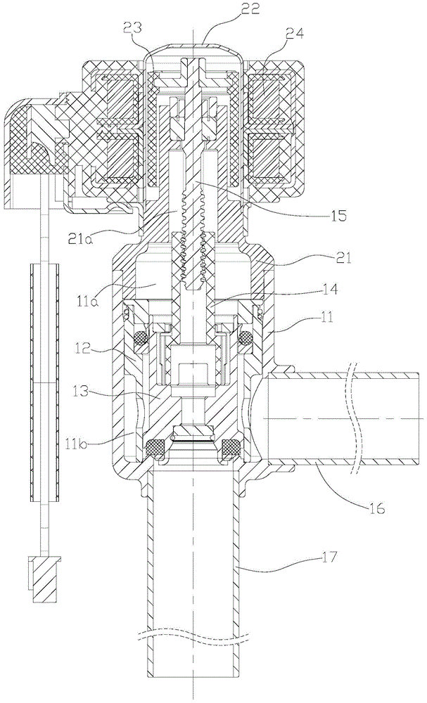
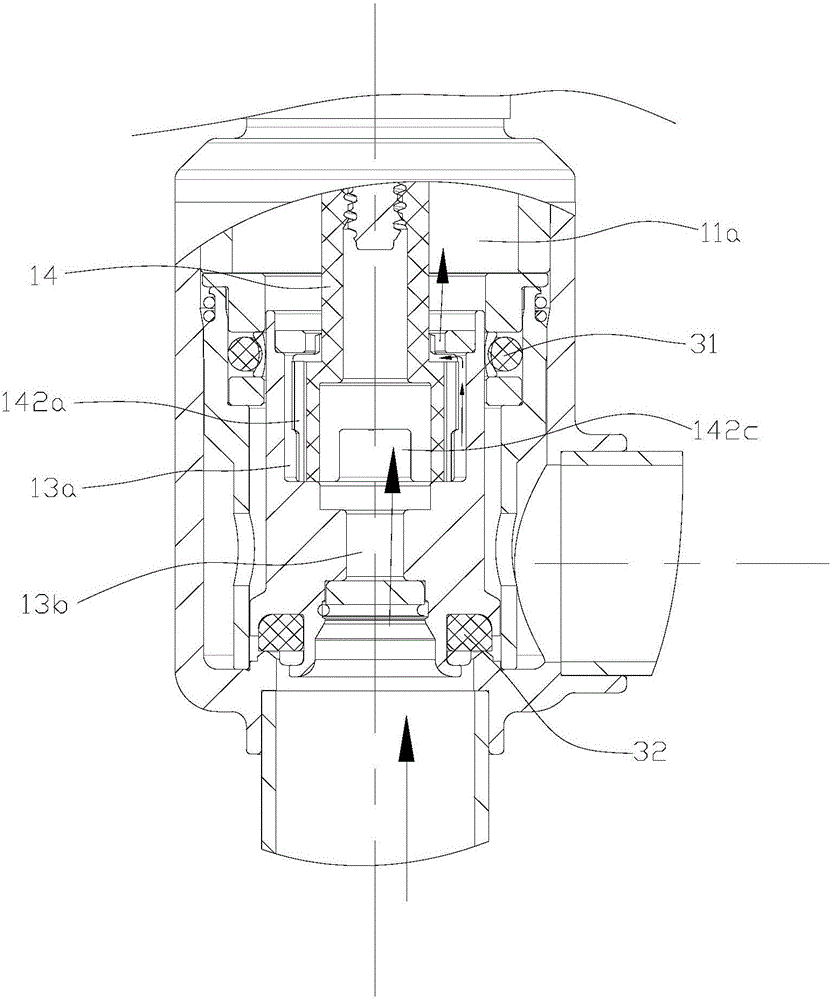
[0030] Please refer to figure 1 and figure 2 , figure 1 It is a cross-sectional schematic diagram of a specific embodiment of the direct-acting electric valve provided by the present invention; figure 2 A schematic diagram of the structure of the balanced flow channel in the fully closed state of the valve core is shown.

[0031] In this embodiment, the direct-acting electric valve includes a valve seat 11 with a valve cavity, a valve seat ...


PUM


Abstract

The invention discloses a direct-acting electric valve comprising a valve seat having a valve cavity and a valve core disposed in the valve seat. The valve cavity is divided into an upper cavity and a lower cavity by the valve core; the valve core is connected with a nut; the valve core driven by the nut can axially move to be arranged on a valve port of the valve seat in an opening or a close way; the nut is formed by a small diameter part and a large diameter part arranged on the lower end of the small diameter part; at least one through groove communicated with the upper cavity is formed on the peripheral wall of the large diameter part; the valve core is provided with an accommodating cavity accommodating the large diameter part and an axial through hole communicated with the accommodating cavity; the axial through hole is communicated with the valve port; the periphery of the large diameter part is provided with an opening to be communicated with the axial through hole and the through groove; therefore, when air pressure of the valve port is higher or lower than the upper cavity, air pressure balance can be achieved via a flow channel formed by the axial through hole of the valve core, the opening of the large diameter part of the nut and the through groove; the valve core can be prevented from upward or downward pushing force; and impact to the valve core or impedance to the action of the valve core can be prevented.

Description

technical field [0001] The present invention relates to the technical field of fluid control components, in particular to a direct-acting electric valve. Background technique [0002] In air conditioners, refrigerators, heat pump water heaters and various refrigeration and heating equipment or other occasions where fluid flow needs to be adjusted, flow control valves are usually used, and direct-acting electric valves are one of the flow control valves. [0003] At present, a common direct-acting electric valve can realize bidirectional flow, including a valve seat with a valve cavity and a valve seat core set in the valve seat. The valve cavity is divided into a core cavity and a surrounding core cavity by the valve seat core. In the lower compartment of the core cavity, the peripheral wall of the valve seat core is provided with a flow adjustment groove; the bottom of the valve seat is provided with a valve port communicating with the core cavity, and is connected with a v...

Claims


Application Information

Patent Timeline
Patent Type & Authority Patents(China)
IPC IPC(8): F16K1/02F16K1/36F16K31/50
CPCF16K1/02F16K1/36F16K31/50
Inventor 不公告发明人
Owner ZHEJIANG SANHUA COMMERCIAL REFRIGERATION CO LTD
Why Eureka
Try Eureka