Dynamic parameter calibration device and method for photoelectric sight-stabilizing system stability measurement device

A system stabilization and measurement device technology, applied in the field of optical testing, can solve the problems of inability to reflect the dynamic characteristics of the system, calibration, and unsuitable for the dynamic parameters of the photoelectric stabilization system, so as to solve the dynamic parameter calibration and achieve the effect of dynamic angle deflection.

Active Publication Date: 2017-12-26
THE 41ST INST OF CHINA ELECTRONICS TECH GRP
View PDF9 Cites 6 Cited by
  • Summary
  • Abstract
  • Description
  • Claims
  • Application Information

AI Technical Summary

Problems solved by technology
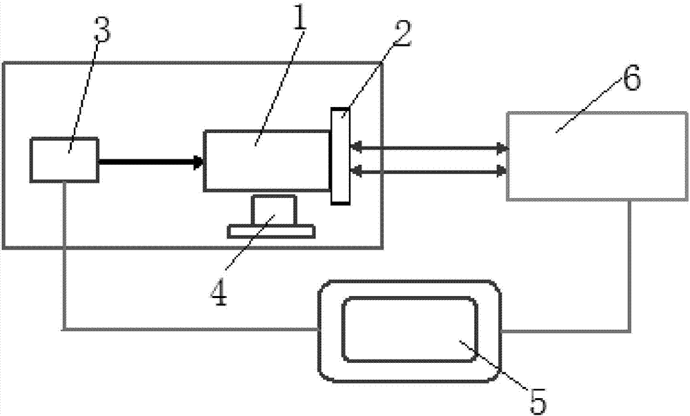
[0004] At present, most of the photoelectric stabilization system stability measurement devices established by scientific research institutes and testing departments are special-purpose testing equipment. In order to ensure reliable performance and accurate and unified parameter values, it is necessary to solve the problem of traceability. The photoelectric autocollimator has established some calibration specifications and calibration devices, but these calibration devices mainly solve the small-angle traceability under static conditions, and are not suitable for the dynamic parameter calibration of the stability measurement device of the photoelectric stabilization system. At the same time, some test documents The photoelectric theodolite was used to calibrate the stability measurement device of the photoelectric stabilization system, but only the angle calibration was completed, and it could not reflect the dynamic characteristics of the system, so it was difficult to meet the requirements
[0005] To sum up, in the prior art, there is still no effective solution for the calibration of dynamic parameters suitable for the stability measurement device of the electro-optical stabilization system.

Method used


Image

  • Dynamic parameter calibration device and method for photoelectric sight-stabilizing system stability measurement device
  • Dynamic parameter calibration device and method for photoelectric sight-stabilizing system stability measurement device
  • Dynamic parameter calibration device and method for photoelectric sight-stabilizing system stability measurement device

Examples


Embodiment Construction

[0051] It should be pointed out that the following detailed description is exemplary and intended to provide further explanation to the present application. Unless defined otherwise, all technical and scientific terms used herein have the same meaning as commonly understood by one of ordinary skill in the art to which this application belongs.

[0052] It should be noted that the terminology used here is only for describing specific implementations, and is not intended to limit the exemplary implementations according to the present application. As used herein, unless the context clearly dictates otherwise, the singular is intended to include the plural, and it should also be understood that when the terms "comprising" and / or "comprising" are used in this specification, they mean There are features, steps, operations, means, components and / or combinations thereof.

[0053] As introduced in the background technology, there is insufficient calibration of dynamic parameters in th...


PUM


Abstract

The invention discloses a dynamic parameter calibration device and method for a photoelectric sight-stabilizing system stability measurement device. The calibrated photoelectric sight-stabilizing system stability measurement device is fixed onto a photoelectric platform to build a micro-vibration generator, the micro-vibration generator is started, an image acquisition system of the calibrated photoelectric sight-stabilizing system stability measurement device is opened, the positions of self-collimation light spots returned by an optical lens are acquired by the image acquisition system, the positions of reference image light spots are transmitted to a processing computer, vibration frequency and angle offset range of the micro-vibration generator are set, so that light beams entering the optical lens generate offset, the positions of offset image light spots returned by the optical lens are acquired by the image acquisition system, and offset angles of the light spots are calculated. According to the device, the photoelectric sight-stabilizing system stability measurement device is dynamically calibrated, and dynamic parameter calibration of the photoelectric sight-stabilizing system stability measurement device is achieved.

Description

technical field [0001] The invention belongs to the field of optical testing, and in particular relates to a dynamic parameter calibration device and method suitable for a stability measurement device of a photoelectric stabilization system. Background technique [0002] Airborne, vehicle-mounted, and ship-borne optoelectronic platforms have multi-directional, all-weather, high-tech reconnaissance and precision strike capabilities. As a fast and intuitive channel and means of obtaining information, they are widely used in military reconnaissance, space remote sensing, disaster forecasting, resource detection and other fields . As an important part of the optoelectronic platform, the photoelectric stabilization system has the function of line of sight stabilization or image stabilization to achieve precise aiming and tracking of targets, and then achieve precise strikes on targets. It is the key to modern optoelectronic weapons and equipment to achieve precise strikes techno...

Claims


Application Information

Patent Timeline
Patent Type & Authority Applications(China)
IPC IPC(8): G01M11/00
CPCG01M11/00
Inventor 赵发财孙权社王国权韩忠王少水郑翔亮
Owner THE 41ST INST OF CHINA ELECTRONICS TECH GRP
Why Eureka
Try Eureka