Dynamic calibration method for linearity of collision force measurement force sensor

A force sensor and dynamic calibration technology, which is applied in the direction of force/torque/power measuring instrument calibration/testing, measuring devices, instruments, etc., can solve the problem of not establishing a complete, consistent, and pulse-type force source that cannot guarantee the force condition and normality Situation and other issues

Inactive Publication Date: 2020-04-17
CHANGSHA UNIVERSITY OF SCIENCE AND TECHNOLOGY
View PDF8 Cites 1 Cited by
  • Summary
  • Abstract
  • Description
  • Claims
  • Application Information

AI Technical Summary

Problems solved by technology

[0006] The calibration methods currently used for the linearity of force sensors can be divided into three categories: step type, pulse type, and sinusoidal type according to the different excitation forms of the dynamic force generating devices. However, if these dynamic force generating devices are used to measure the collision force There are many deficiencies in the calibration of force sensors, such as the accuracy of the sinusoidal force generated by the vibrating table-type sine force source is not high enough, and the force value is not large enough; the step-type force source has the problem of non-standard amplitude sensitivity calibration method; the pulse-type force source cannot guarantee The force condition of the equipment under high-speed impact is consistent with the normal situation, which is easy to cause large errors. At present, there is no complete force sensor calibration / calibration system for measuring collision force in China. This is mainly because it affects the force sensor for measuring collision force. There are many factors for calibration / calibration, especially the loading conditions of the collision force, the installation environment of the sensor, the structural parameters of the equipment, etc.; with the development of traffic safety technology, the detection content of the anti-destruction ability of the equipment has been born, which needs to detect the anti-collision structure Correspondingly, the resistance under destructive collision conditions requires a collision force measurement system and a dynamic calibration method for force sensors that meet the requirements of the collision force loading conditions, equipment installation environment, and equipment structural parameters. The dynamic calibration of the linearity of the force sensor for collision force measurement, the calibration result obtained is closer to the actual working state of the force sensor

Method used


Image

  • Dynamic calibration method for linearity of collision force measurement force sensor
  • Dynamic calibration method for linearity of collision force measurement force sensor
  • Dynamic calibration method for linearity of collision force measurement force sensor

Examples


Embodiment 1

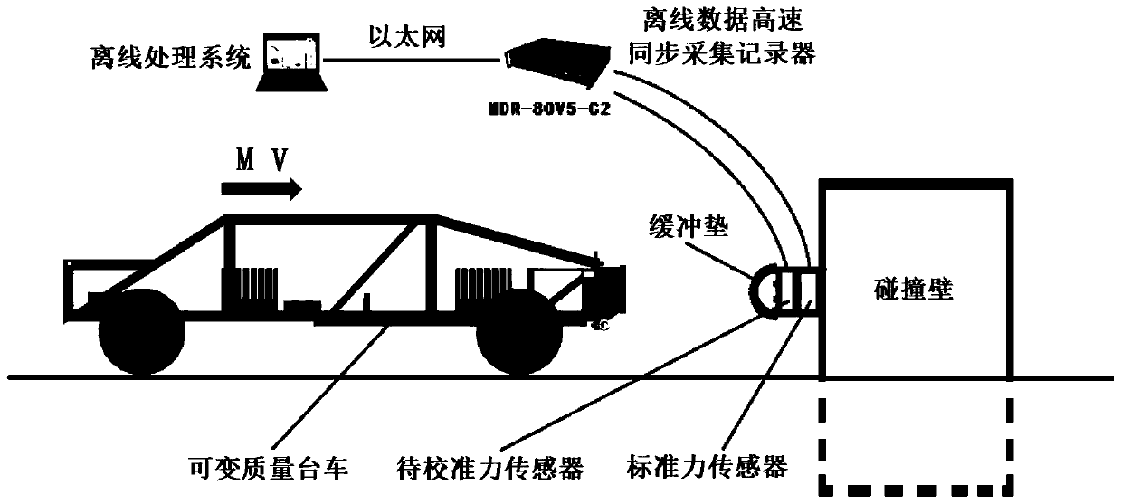
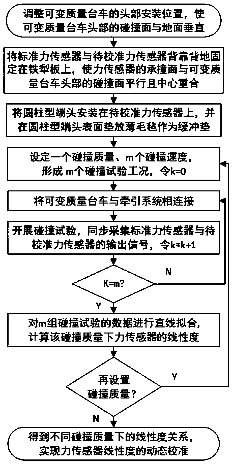
[0063] Embodiment 1, this embodiment discloses a dynamic calibration method for the linearity of the force sensor used to measure the impact force. The schematic diagram of the dynamic calibration system is as follows figure 1 As shown, the flow chart of the dynamic calibration method is as follows figure 2 As shown, the specific implementation steps are as follows:

[0064] S1: By padding different thicknesses and different numbers of spacers between the variable mass trolley and its head, the collision surface of the variable mass trolley head is perpendicular to the ground.

[0065] S2: Use the order of placing the standard force sensor close to the iron plowboard, and the force sensor to be calibrated close to the standard force sensor, and rigidly connect the force sensor to be calibrated and the standard force sensor to the iron plow in a back-to-back horizontal stacking manner board. By placing different thicknesses and different numbers of gaskets at different posit...


PUM


Abstract

The invention discloses a dynamic calibration method for the linearity of a collision force measurement force sensor. The implementation method comprises the steps that the head installation positionof the variable-mass trolley is adjusted till the collision face is perpendicular to the ground; fixing a standard sensor and a sensor to be calibrated on the iron plough plate embedded in the collision wall in a back-to-back manner, so that the collision bearing surface is parallel to the collision surface of the trolley, and the centers of the collision bearing surface and the collision surfacecoincide; installing the end head with the buffer pad on the sensor to be calibrated; setting a collision mass and collision speed range to form m groups of test working conditions with unchanged collision mass and speed from small to large; the trolley is connected with the traction system to realize the set test, and output signals of the two sensors are synchronously acquired; fitting data in astraight line; calculating a nonlinear deviation maximum value under a certain collision mass according to the fitting equation, and calculating the linearity of the sensor under the collision mass according to the nonlinear deviation maximum value; changing the collision mass, repeating the above steps, and obtaining the linearity and linearity relation under different collision masses, therebyrealizing the dynamic calibration.

Description

technical field [0001] The invention relates to a dynamic calibration method for the linearity of a force sensor used for collision force measurement, and belongs to the field of force sensor calibration methods. Background technique [0002] Linearity, also known as nonlinearity, characterizes the degree of deviation between the sensor output-input calibration curve (or average calibration curve) and the selected fitting straight line as the working straight line. This index is usually expressed as a relative error: [0003] [0004] In formula (4): ξ L is linearity; ΔL max is the maximum deviation between the output average calibration curve and the fitted straight line; [0005] the y F.S is the theoretical full-scale output. [0006] The calibration methods currently used for the linearity of force sensors can be divided into three categories: step type, pulse type, and sinusoidal type according to the different excitation forms of the dynamic force generating dev...

Claims


Application Information

Patent Timeline
Patent Type & Authority Applications(China)
IPC IPC(8): G01L25/00G01M7/08
CPCG01L25/00G01M7/08
Inventor 涂晓威雷正保
Owner CHANGSHA UNIVERSITY OF SCIENCE AND TECHNOLOGY
Why Eureka
Try Eureka