POE power supply-based integrated driving motor

A technology for driving motors and driving power, which is applied in the direction of connection with control/drive circuits, electric components, electrical components, etc., to achieve the effect of reducing product cost, small loop area, and saving connectors

Pending Publication Date: 2017-12-26
SHANGHAI ANPU MINGZHI AUTOMATION EQUIP
View PDF6 Cites 0 Cited by
  • Summary
  • Abstract
  • Description
  • Claims
  • Application Information

AI Technical Summary

Problems solved by technology

However, this requires a dedicated power supply harness and a dedicated power supply connector

Method used


Image

  • POE power supply-based integrated driving motor
  • POE power supply-based integrated driving motor
  • POE power supply-based integrated driving motor

Examples


Embodiment Construction

[0024] The following will clearly and completely describe the technical solutions in the embodiments of the present invention with reference to the drawings in the embodiments of the present invention. Obviously, the described embodiments are part of the embodiments of the present invention, not all of them. Based on the embodiments of the present invention, all other embodiments obtained by persons of ordinary skill in the art without making creative efforts shall fall within the protection scope of the present invention.

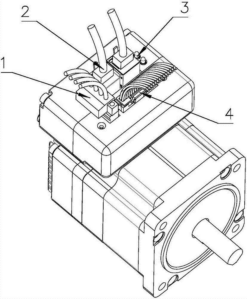
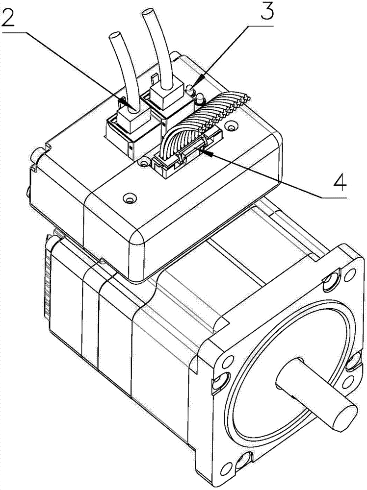
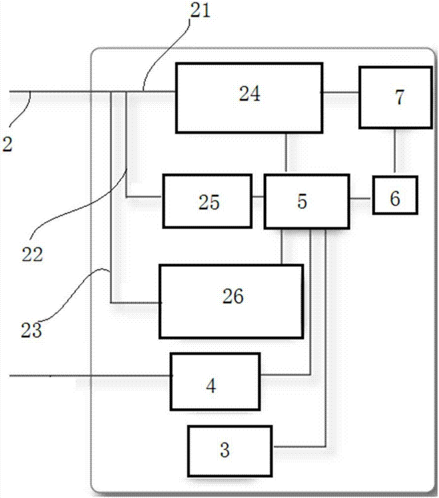
[0025] Such as figure 2 As shown, an integrated drive motor based on POE power supply includes a motor body and a driver connected to the motor body. The driver includes a drive circuit board and a status indicator light 3 and an IO connector 4 respectively connected to the drive circuit board. The driver described above also includes a POE power supply system connected to the driver circuit board. The Ethernet connector can be used for all Ethernet conn...


PUM


Abstract

The invention relates to a POE power supply-based integrated driving motor comprising a motor body and a driver connected with the motor body; the driver comprises a driving circuit board, a state indicating lamp and an IO connector; the state indicating lamp and the IO connector are connected with the driving circuit board; the driver also comprises a POE power supply system connected with the driving circuit board. Compared with technologies of the prior art, the POE power supply-based integrated driving motor is advantaged by simple structure, good universality, low implementation cost and the like.

Description

technical field [0001] The invention relates to an integrated motor, in particular to an integrated drive motor powered by POE. Background technique [0002] The integrated motor system is composed of motor, feedback system (optional), drive amplifier, motion controller, communication control module and other subsystems. The integrated motor in the prior art provides power from the outside, and converts the power supply into a low-voltage power supply for the motion control part through the power module of the driving amplifier, and outputs the current for driving the motor through the power electronic part of the driving amplifier. Generally, the control method commonly used in the integrated motor often uses the Ethernet interface to send control commands according to the agreed communication protocol to control the operation of the motor. as attached figure 1 shown. figure 1 As shown in , 1 is the power connector, 2 is the Ethernet connector, 3 is the status indicator ...

Claims


Application Information

Patent Timeline
Patent Type & Authority Applications(China)
IPC IPC(8): H02K11/33H02K11/00H04L12/10
CPCH02K11/0094H04L12/10H02K2211/03
Inventor 杨剑
Owner SHANGHAI ANPU MINGZHI AUTOMATION EQUIP
Why Eureka
Try Eureka