
Shaft shoulder positioning tip for grinding machine

A technology of tip and shoulder, applied in the field of shaft shoulder positioning for grinding machine, can solve the problems of low processing efficiency and high production cost, and achieve the effects of easy movement, reduced friction, and elimination of gaps

Inactive Publication Date: 2017-12-29
河南省瑞歌传动机械有限公司
View PDF0 Cites 0 Cited by
  • Summary
  • Abstract
  • Description
  • Claims
  • Application Information

AI Technical Summary

Problems solved by technology

[0005] Aiming at the deficiencies of the prior art, the present invention provides a shoulder positioning tip for a grinding machine, which solves the problem that the existing machine tool using the shoulder measurement and positioning must be a numerical control machine tool, which cannot be used on an ordinary grinding machine, which causes product failure. High production cost and low processing efficiency

Method used


Image

  • Shaft shoulder positioning tip for grinding machine
  • Shaft shoulder positioning tip for grinding machine

Examples


Embodiment Construction

[0027] The following will clearly and completely describe the technical solutions in the embodiments of the present invention with reference to the accompanying drawings in the embodiments of the present invention. Obviously, the described embodiments are only some, not all, embodiments of the present invention. Based on the embodiments of the present invention, all other embodiments obtained by persons of ordinary skill in the art without making creative efforts belong to the protection scope of the present invention.

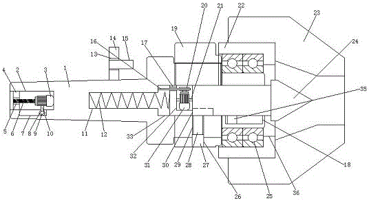
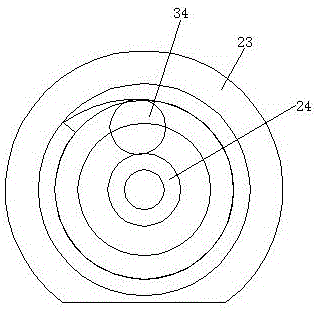
[0028] An embodiment of the present invention provides a shoulder positioning tip for a grinding machine, such as Figure 1-2As shown, it includes the top body 1 and the positioning sleeve 23, the interior of the top body 1 and the positioning sleeve 23 are inserted, the surface of the top body 1 is sleeved with a bearing 25, the surface of the bearing 25 is sleeved with a rotary positioning sleeve 22, and the rotary positioning sleeve The surface of 22 is fix...


PUM


Abstract

The invention provides a shaft shoulder positioning top for a grinding machine, and relates to the field of shaft shoulder positioning tops. The grinding machine uses a shaft shoulder to position the top, including a top body and a positioning sleeve. The top body is inserted into the interior of the positioning sleeve. The surface of the top body is sleeved with a bearing, and the surface of the bearing is sleeved with a rotary positioning sleeve. The surface of the rotary positioning sleeve is fixedly connected with the inner wall of the positioning sleeve, and the surface of the top body is provided with a locking sleeve on the left side of the rotary positioning sleeve, and the left side of the locking sleeve is connected to the right side of the top body. Overlapping, the right side of the top body is provided with an active slot. The grinding machine uses the shaft shoulder to locate the top, and the movable motor drives the screw to rotate, so that the screw can realize the effect of tightening and installing the top body on the ordinary grinding machine and the CNC grinding machine. Through the cooperation between the screw and the screw hole, the screw can move to the left. The rod runs through the fixing hole inside the fixing plate to increase the stability of the top machine body installed on the grinding machine.

Description

technical field [0001] The invention relates to the technical field of shoulder positioning tip, in particular to a shoulder positioning tip for a grinding machine. Background technique [0002] In the 1830s, in order to adapt to the processing of parts such as clocks, bicycles, sewing machines and firearms after hardening, Britain, Germany and the United States developed grinding machines using natural abrasive emery wheels respectively. Grinding machines use abrasive tools to grind the workpiece surface of machine tools. Most grinding machines use high-speed rotating grinding wheels for grinding, and a few use other abrasive tools such as oil stones and abrasive belts and free abrasives for processing, such as honing machines, superfinishing machine tools, abrasive belt grinders, grinding machines and polishing Machines, etc., need to use the shoulder positioning center for positioning during grinding machine processing, and the shaft shoulder positioning center is mainly...

Claims


Application Information

Patent Timeline
Patent Type & Authority Applications(China)
IPC IPC(8): B24B5/35B24B5/04B24B41/06
CPCB24B5/35B24B5/04B24B41/061
Inventor 王志东王冲翟战军姚伟杰杨建伟王积康古成超王龙涛
Owner 河南省瑞歌传动机械有限公司
Learn More