
Conveniently-replaced machine barrel screw for injection molding device

A technology that is convenient for replacement and injection molding equipment, applied in the field of barrel and screw, can solve the problems of wasting time, failing to meet the needs of use, increasing costs, etc., and achieve the effects of reducing production costs, meeting needs of use, and improving production efficiency

Inactive Publication Date: 2017-12-29
宁波金亿精密机械有限公司
View PDF3 Cites 2 Cited by
  • Summary
  • Abstract
  • Description
  • Claims
  • Application Information

AI Technical Summary

Problems solved by technology

[0003] The threads of the barrel and screw are divided into different areas. For different raw materials or different finished product requirements, the thread distribution ratio of the barrel and screw is different. Therefore, in the process of injection molding production, it is often necessary to replace the barrel and screw, while the existing injection molding The barrel and screw used in the equipment are all one-piece rods. When replacing, the entire screw needs to be disassembled, which wastes a lot of time, and many types of screws need to be spared, which increases the cost and cannot meet the needs of people in production and life.

Method used


Image

  • Conveniently-replaced machine barrel screw for injection molding device
  • Conveniently-replaced machine barrel screw for injection molding device

Examples


Embodiment Construction

[0017] The following will clearly and completely describe the technical solutions in the embodiments of the present invention with reference to the accompanying drawings in the embodiments of the present invention. Obviously, the described embodiments are only some, not all, embodiments of the present invention.

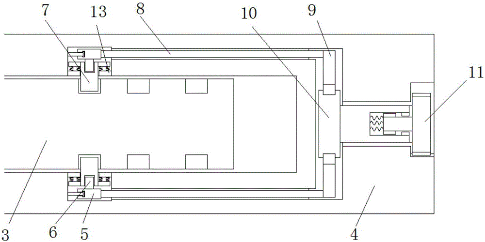
[0018] refer to Figure 1-2 , a barrel screw for injection molding equipment that is easy to replace, including a screw head 1, a screw sub-cylinder body 2, a central column 3 and a connecting head 4, there are multiple screw sub-cylinder bodies 2, and the screw sub-cylinder body 2 and the connecting head 4 are provided with through holes, one end of the center column 3 is fixedly welded to one end of the screw head 1, the screw sub-cylinder body 2 is set on the outside of the center column 3, and the connector 4 is connected to the end of the center column 3 away from the screw head 1, The cylinder of the middle column 3 is provided with several groups of card slots...


PUM


Abstract

The invention discloses a conveniently-replaced machine barrel screw for an injection molding device. The conveniently-replaced machine barrel screw comprises a screw head, screw branch cylinders, a middle pillar and a connecting head. The multiple screw branch cylinders are arranged, and through holes are formed in the screw branch cylinders and the connecting head. One end of the middle pillar is fixed and welded to one end of the screw head. The screw branch cylinders are arranged on the outer side of the middle pillar in a sleeving manner. The connecting head is connected with the end, away from the screw head of the middle pillar. Multiple sets of clamping grooves are formed in a pillar body of the middle pillar. Side grooves are formed in the inner wall of the through hole of the connecting head, and rotation pillars are rotationally connected to the inner wall of the sides, close to the screw head, of the side grooves. Adjusting rods are connected to the sides, close to each other, of the rotation pillars. The ends, close to each other, of the adjusting rods are connected with clamping rods in a contact manner. By means of the conveniently-replaced machine barrel screw for the injection molding device, the demounting step is omitted, the production efficiency is improved, meanwhile, a large amount of different types of machine barrel screws are not needed in a production workshop, the production cost is reduced, and the use requirement of people in production and life is met.

Description

technical field [0001] The invention relates to the technical field of injection molding, in particular to an easily replaceable barrel and screw for injection molding equipment. Background technique [0002] The barrel is the same as in the extrusion compression molding system, and it is an important part of the extruder. The barrel and the screw work together, the barrel contains the screw, and the screw rotates in the barrel. When the screw rotates and pushes the plastic to move forward in the barrel, the heat is transferred from the outside of the barrel to the plastic in the barrel, and the volume of the thread on the screw gradually shrinks, so that the plastic in the thread groove is squeezed, turned and sheared. After the action of various forces such as cutting, it is uniformly mixed and plasticized, and as it moves to the front of the barrel, it gradually melts into a viscous flow state to complete the plasticization of the plastic. The normal cooperation between...

Claims


Application Information

Patent Timeline
IPC IPC(8): B29C45/60
CPCB29C45/60
Inventor 张朝波张彦富赵子明赵锐刘驰虹梁艳秋
Owner 宁波金亿精密机械有限公司
Learn More