Lead deicing system used for high voltage power transmission and transformation project

A technology for power transmission and transformation, applied in the field of wire deicing systems for high-voltage power transmission and transformation projects, can solve problems such as inconvenient use, and achieve the effects of energy saving, appropriate distance, good strength and frequency

Active Publication Date: 2017-12-29
STATE GRID CORP OF CHINA +1
View PDF8 Cites 10 Cited by
  • Summary
  • Abstract
  • Description
  • Claims
  • Application Information

AI Technical Summary

Problems solved by technology

Although the deicing effect of this invention is very good, it is ...

Method used


Image

  • Lead deicing system used for high voltage power transmission and transformation project
  • Lead deicing system used for high voltage power transmission and transformation project
  • Lead deicing system used for high voltage power transmission and transformation project

Examples


Embodiment 1

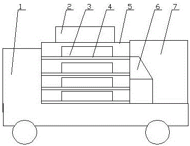
[0047] Embodiment one, such as figure 1 As shown, the present invention provides a wire deicing system for high-voltage power transmission and transformation engineering, including a carrier vehicle 1, a compartment 5 is arranged at the rear of the carrier vehicle 1, a shelf 4 is arranged in the compartment 5, and a shelf 4 is arranged inside the shelf 4. Several self-propelled de-icing devices 3 are set, a control room 7 is set at the rear of the compartment 5, a console 6 is arranged in the control room 7, an unmanned aerial vehicle 2 is arranged on the top of the compartment 5, and the unmanned aerial vehicle 2 The lower part is provided with a fixing mechanism corresponding to the self-propelled de-icing device 3, and the console 6 is connected with the signal of the drone 2 and the self-propelled de-icing device 3, and the self-propelled de-icing device 3 includes a walking mechanism , a deicing mechanism is set on the walking mechanism.

[0048] The bottom plate 21 is p...

Embodiment 2

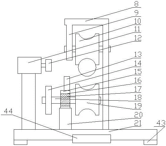
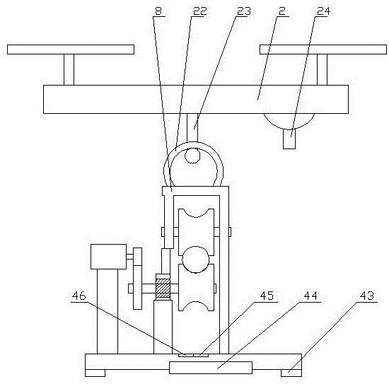
[0053] like figure 2 and image 3 As shown, the difference between this embodiment and Embodiment 1 is:

[0054] Described walking mechanism comprises base plate 21, and the top of described base plate 21 two ends is provided with L-shaped support 8, and the top of described L-shaped support 8 is provided with mounting rod 9 downwards, and described mounting rod 9 and described L-shaped support 8 are provided with Pulley 10, telescoping mechanism 20 is set on described base plate 21 below described installation bar 9, and the upper end of described telescoping mechanism 20 is provided with installation block 15, and vertical stop bar 13 is set on described installation block 15, and described installation A mounting hole 16 is arranged in the middle of the block 15, and a rotating shaft 18 parallel to the central axis of the pulley 10 is set through a bearing 17 in the mounting hole 16, and a driving wheel 19 matched with the pulley 10 is arranged on the rotating shaft 18. ...

Embodiment 3

[0061] like Figure 4 to Figure 7 As shown, the difference between this embodiment and Embodiment 1 is:

[0062] The deicing mechanism includes an icicle removal mechanism and an ice film removal mechanism. The icicle removal mechanism includes a column 28 provided at the front end of the base plate 21, a launch tube 25 is provided at the upper end of the column 28, and a launch tube 25 is provided at the end of the launch tube 25. Compression spring 30, the front end of the compression spring 30 is connected with a push rod 26, the launching tube 25 is provided with a fixing groove 27, the push rod 26 is provided with a slider 29 passing through the fixing groove 27, and the slider 29 When contacting with the front end of the fixing groove 27, the ejector stick 26 stretches out from the launch tube 25, and a second drive mechanism is set on the bottom plate corresponding to the slider 29, and the second drive mechanism includes a set on the bottom plate 21. The driving motor...


PUM


Abstract

The invention provides a lead deicing system used for a high voltage power transmission and transformation project. The lead deicing system comprises a carrying vehicle. The rear part of the carrying vehicle is provided with a compartment which is internally provided with shelves. The shelves are internally provided with multiple self-propelled deicing devices. The rear part of the compartment is provided with a control room which is internally provided with a console. The top part of the compartment is provided with an unmanned aerial vehicle. The lower part of the unmanned aerial vehicle is provided with fixing mechanisms in a way of being corresponding to the self-propelled deicing devices. The console is connected with the unmanned aerial vehicle and the self-propelled deicing devices in a signaling way. Each self-propelled deicing device comprises a walking mechanism which is provided with a deicing mechanism. The deicing mechanism is provided with an adjusting mechanism on which a wind swing is arranged. The ice on the power transmission line can be automatically removed, and the work personnel arrange the deicing devices on each section of power transmission line through the unmanned aerial vehicle and then recover the deicing devices together so that the efficiency is quite high and the labor input is low. Besides, the adjusting mechanism on which the wind swing is arranged is installed so that efficient line deicing can also be solved within the extreme event and the safety can also be ensured.

Description

technical field [0001] The invention relates to the technical field of deicing power transmission lines, in particular to a wire deicing system for high-voltage power transmission and transformation projects. Background technique [0002] The medium for long-distance transmission of electricity near the transmission grid generally adopts high-voltage lines to improve the efficiency of power transmission. However, when the temperature drops below zero, the freezing of water will cause damage to the lines, iron towers, and iron tower foundations. The work brings great inconvenience and also causes huge losses to regional economic development. Due to the particularity of the high-voltage line, the traditional manual deicing method at this time will not only reduce the deicing efficiency, but also easily cause casualties. [0003] In the prior art, one solution for deicing high-voltage lines is to "put on" a layer of super-hydrophobic coating "coat" for high-voltage lines when ...

Claims


Application Information

Patent Timeline
IPC IPC(8): H02G7/16
CPCH02G7/16
Inventor 孟凡斌周正樊庆玲陈晨郭静宋景博赵志虎郭兴武李凯石钧
Owner STATE GRID CORP OF CHINA
Why Eureka
Try Eureka