A self-locking method for power supply of fly-by-wire flight control system

A fly-by-wire flight control system and self-locking technology, which is applied in the field of power supply and self-locking of the fly-by-wire system, can solve the problems of misoperation of power switch, affecting flight safety, hidden danger of common mode/single point failure, etc., so as to reduce failures. hidden effect

Active Publication Date: 2020-11-24
JIANGXI HONGDU AVIATION IND GRP
View PDF2 Cites 0 Cited by
  • Summary
  • Abstract
  • Description
  • Claims
  • Application Information

AI Technical Summary

Problems solved by technology

[0003] 1) Since the power switch components, cables, cable connectors, etc. are physically a single structural part, there are hidden dangers of common mode / single point failure, which will easily lead to power failure of the fly-by-wire flight control system when a failure occurs;
[0004] 2) Misoperation of the power switch by the pilot may easily cause the power supply failure of the fly-by-wire flight control system;
[0005] During the flight training process, the power supply of the fly-by-wire flight control system fails, which will directly affect the flight safety, and in serious cases cause the aircraft to crash

Method used


Image

  • A self-locking method for power supply of fly-by-wire flight control system

Examples


Embodiment Construction

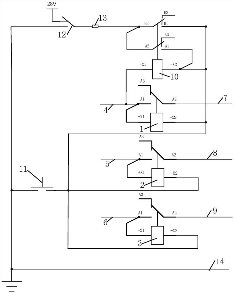
[0018] In order to make the technical means, creative features, goals and effects achieved by the present invention easy to understand, the present invention will be further described below in conjunction with specific illustrations.

[0019] see figure 1 A power supply self-locking method for the fly-by-wire flight control system, first connect the fly-by-wire flight control system through the left generator, right generator and battery of the aircraft at the same time, supply DC voltage 28V to the fly-by-wire flight control system, and then use the redundancy strategy To improve the power supply reliability of the system, a three-redundancy power supply line is set up for this purpose, that is, the three redundant input power sources are respectively connected to the left generator, the right generator and the battery of the aircraft, and then three relays (the first relay 1, the second relay The relay 2 and the third relay 3) respectively control the on-off of the three red...


PUM


Abstract

The invention provides a fly-by-wire flight control system power supply self-locking method. Redundant input power supplies are arranged on the left generator, the right generator and the storage battery of an aircraft. The high ends of a first relay, a second relay and a third relay are respectively connected with the first redundant input power supply, the second redundant input power supply and the third redundant input power supply. The low ends of the first relay, the second relay and the third relay are connected with a flight control power switch. The other end of the flight control power switch is connected with the power ground. The normally-closed contacts of the first relay, the second relay and the third relay are respectively connected with a first redundant output power supply, a second redundant output power supply and a third redundant output power supply, and a self-locking relay is arranged on the first relay. The high end of the self-locking relay is connected with the first redundant input power supply. The low end of the self-locking relay is connected with the low end of the first relay. Meanwhile, an aircraft wheel bearing switch is arranged at the signal input end of the self-locking relay so as to meet the requirement of uninterruptible power supply of the fly-by-wire flight control system and reduce the existing fault hidden trouble.

Description

technical field [0001] The invention relates to the technical field of flight control power supply, in particular to a power supply self-locking method for a fly-by-wire flight control system. Background technique [0002] The power supply mode of the fly-by-wire flight control system is manually powered on, that is, the power switch of the fly-by-wire flight control system is manually toggled. During the flight training process, the power switch of the fly-by-wire flight control system has the following potential failures: [0003] 1) Since the power switch components, cables, cable connectors, etc. are physically a single structural part, there are hidden dangers of common mode / single point failure, which will easily lead to power failure of the fly-by-wire flight control system when a failure occurs; [0004] 2) Misoperation of the power switch by the pilot may easily cause the power supply failure of the fly-by-wire flight control system; [0005] During the flight trai...

Claims


Application Information

Patent Timeline
Patent Type & Authority Patents(China)
IPC IPC(8): H02J9/06H02J9/08
CPCH02J9/06H02J9/08
Inventor 杨振声万明刘中剑梁琼花余云鹏杨杰红黄勇强谢慧慈饶明波张欢韩占朋曾行刘欣
Owner JIANGXI HONGDU AVIATION IND GRP
Why Eureka
Try Eureka