Supercharge Your Innovation With Domain-Expert AI Agents!

Ball joint assembly with rotation sensor assembly

A technology of rotating sensor and rotating device, applied in the field of joint group, can solve the problem of not allowing to evaluate and detect the rotation and rotation angle of joint axis

Active Publication Date: 2019-09-06
SAME DEUTZ-FAHR
View PDF6 Cites 0 Cited by
  • Summary
  • Abstract
  • Description
  • Claims
  • Application Information

AI Technical Summary

Problems solved by technology

[0004] The main disadvantage of using ball joints is that it does not allow simple and efficient evaluation and detection of rotation and rotation angles around the joint axis

Method used


Image

  • Ball joint assembly with rotation sensor assembly
  • Ball joint assembly with rotation sensor assembly
  • Ball joint assembly with rotation sensor assembly

Examples


Embodiment Construction

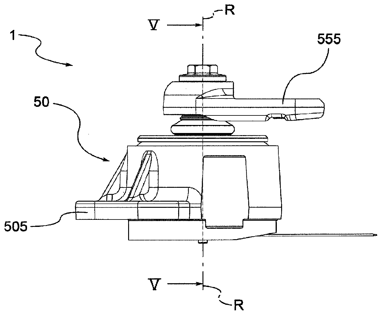
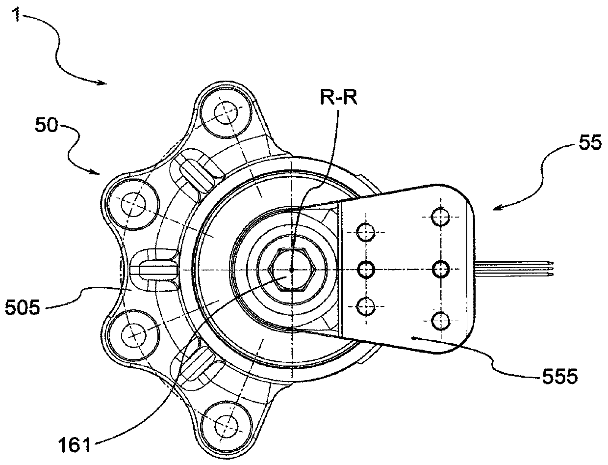
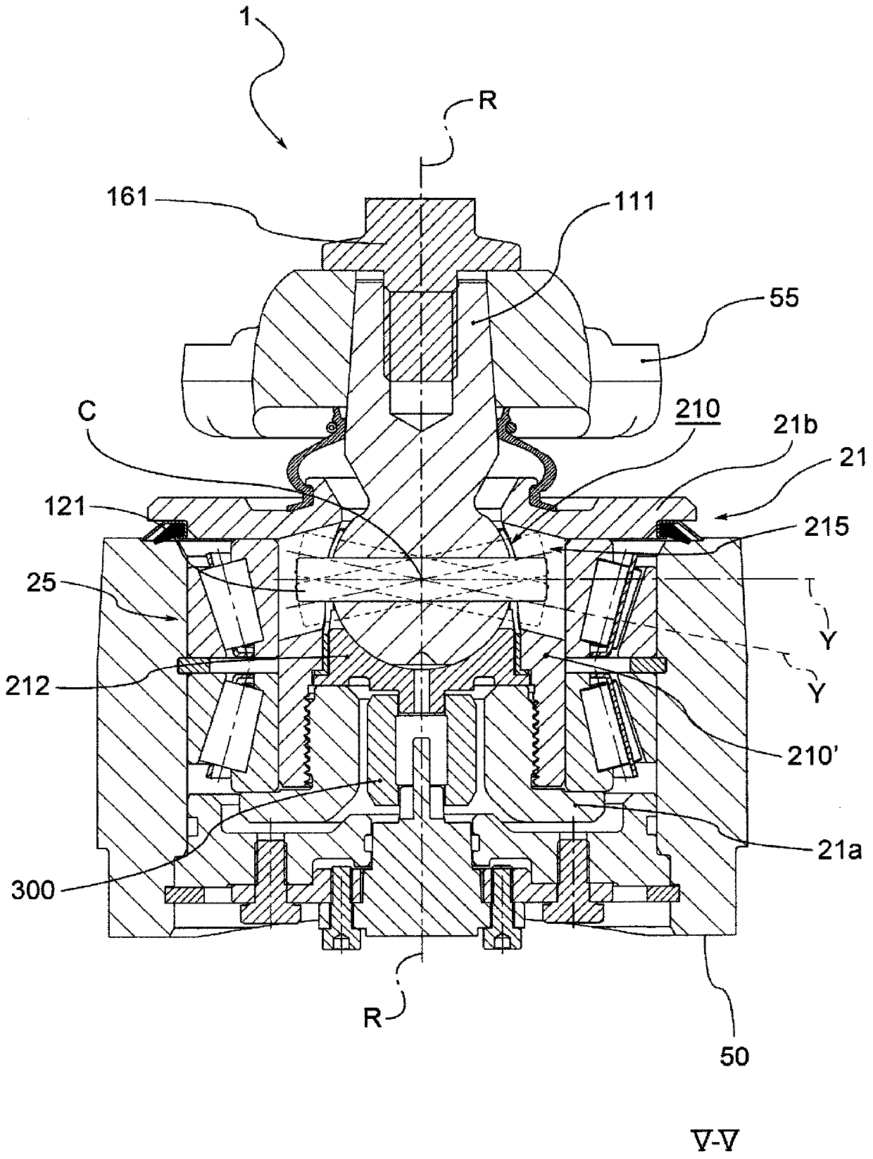
[0013] With reference to the accompanying drawings, the reference numeral 1 generally designates a joint set as a whole according to a preferred embodiment.

[0014] Preferably, the joint set is adapted to operatively connect the first part and the second part. In particular, the joint group 1 is adapted to allow a movement of a first part relative to a second part, wherein said movement is of the rotary type, preferably around the axis of rotation R-R. Thus, by means of the joint set 1 the first part is adapted to rotate relative to the second part and / or vice versa.

[0015] It should be noted that the invention is not limited to the type of components connected to and from the joint set 1 . Any component to which the joint set 1 is attachable is adapted to be operatively connected to another component by the knot set, according to the description given below. For example, in one embodiment the joint set 1 is operatively connected to the jack and the shaft in such a way th...


PUM


Abstract

A joint set (1) for operatively connecting a first part and a second part and allowing reciprocating movement about an axis of rotation (R-R). The joint set (1) comprises: i) a pin (10) having a first end (11) and a second spherical end (12); ii) a swivel device comprising a central body (21) into which is fitted and integrally connected to the second spherical end (12), and the rotation means includes a rotation means (25), adapted to allow free rotation of said central body (21); iii) a rotation sensor means, comprising a detection element, said detection element is adapted to Detecting the angle of rotation of said central body (21); iv) a housing body (50), fixable to said second part, and adapted to accommodate rotation means and rotation sensor means such that the first end of the pin (10) (11) Protrudes to engage the first part.

Description

technical field [0001] The present invention relates to a joint set and a single suspension wheel steering system for an agricultural vehicle including the joint set. Background technique [0002] In mechanics, and generally in mechanical interactions, transformation systems of motion have long been known, in which motion is converted from linear to rotary motion; among various solutions are link-crank systems, or jacks with rotation of the control shaft . [0003] However, usually due to geometrical or mechanical problems, the parts involved in the mutual engagement do not have limited movement in a single axis; in fact, the mutual engagement between the various parts is achieved through the use of ball joints, which by definition allow relative to their Rotational movement of the spherical end in three axes. [0004] The main disadvantage of using ball joints is that they do not allow simple and effective evaluation and detection of rotation and rotation angles about the...

Claims


Application Information

Patent Timeline
Patent Type & Authority Patents(China)
IPC IPC(8): F16C11/06F16C19/38F16C41/00B62D7/18B62D15/02B60B35/00
CPCB62D7/18F16C41/007F16C11/06B62D15/023F16C2326/24F16C11/0685F16C19/364F16C19/543F16C21/00F16C2233/00F16D3/2052
Inventor 洛朗·埃罗代卢卡·斯图基
Owner SAME DEUTZ-FAHR
Features
  • R&D
  • Intellectual Property
  • Life Sciences
  • Materials
  • Tech Scout
  • Unparalleled Data Quality
  • Higher Quality Content
  • 60% Fewer Hallucinations
Learn More