Method for controlling synchronization and shifting

A control method and spindle technology, applied in transmission control, transportation and packaging, components with teeth, etc., can solve the problems of mechanical parts wear and torque fluctuations, and achieve the elimination of torque fluctuations and avoid excessive wear Effect

Active Publication Date: 2019-07-09
RENAULT SAS
View PDF7 Cites 0 Cited by
  • Summary
  • Abstract
  • Description
  • Claims
  • Application Information

AI Technical Summary

Problems solved by technology

The main difficulty arises when braking is applied on steep slopes, where this method cannot avoid torque fluctuations in the coupling process, causing, among other problems, undesired wear on the mechanical parts involved

Method used


Image

  • Method for controlling synchronization and shifting
  • Method for controlling synchronization and shifting
  • Method for controlling synchronization and shifting

Examples


Embodiment Construction

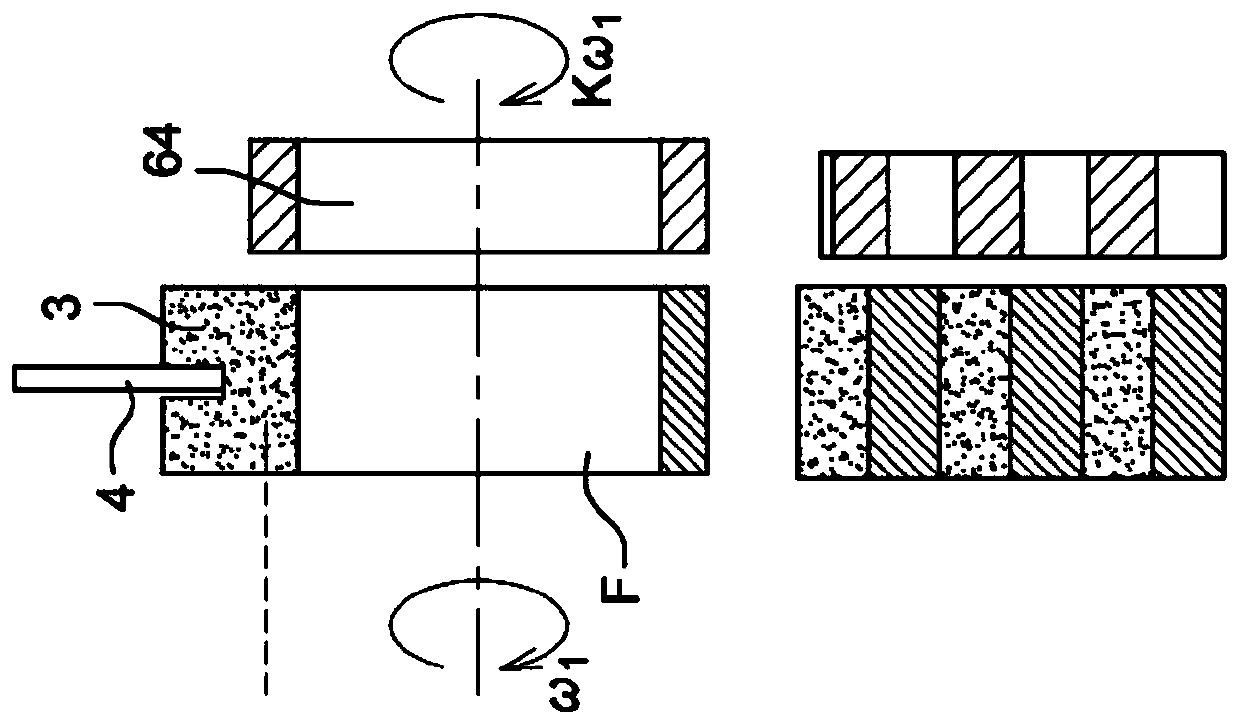
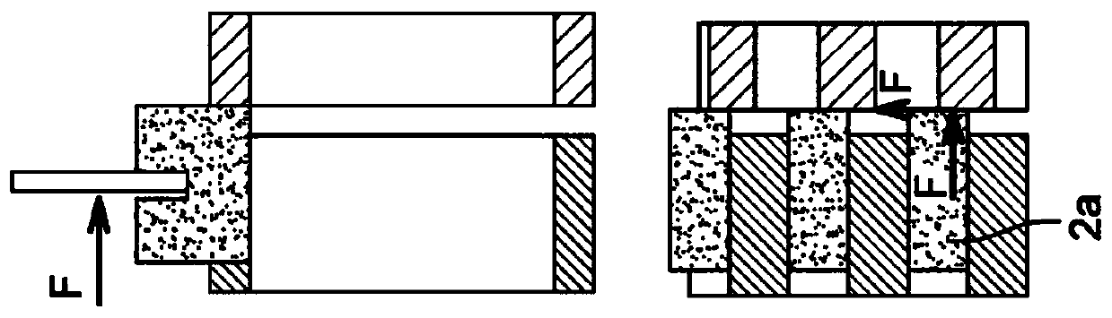
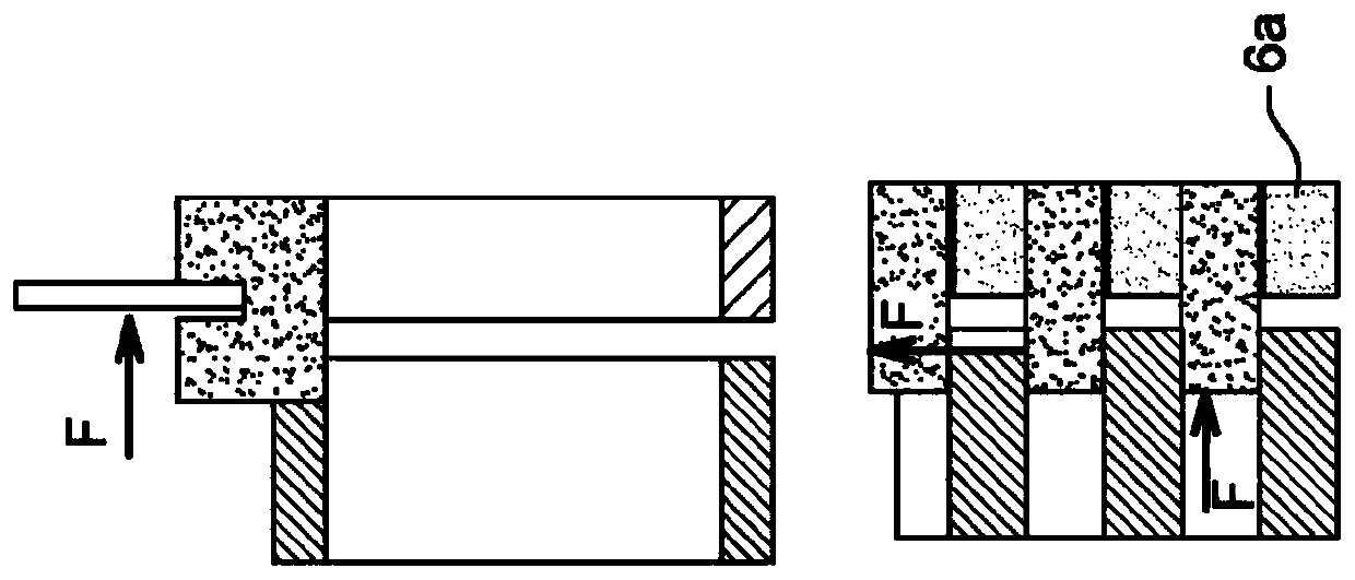
[0015] Figure 1A to Figure 1C The shift slide 2 and its sleeve 3 , its actuating fork 4 and pinion 6 are schematically shown. The lower part of these figures also shows the teeth 2a and 6a of the slide gear and pinion. Sliding gear 2 and pinion 3 are coaxial on a gearbox main shaft (not shown) connected to the vehicle's energy source (traction machine). The pinion 6 is rotationally connected to a gearbox layshaft which is connected to the wheels of the vehicle.

[0016] Figure 1A The initial state of the system at dead point is shown. Sliding gear 2 at the speed of the main shaft ω 1 to rotate. Pinion 6 at a speed ω determined by the countershaft of the gearbox 2 is rotated, the velocity is related to ω 1 different. exist Figure 1B , the slide gear 2 is moved until its teeth 2 a meet those of the pinion 6 . When their rotational speeds are equal, that is to say, at the end of the synchronous phase, the teeth of the sliding gear are interspersed between those of the...


PUM


Abstract

A method for controlling the synchronization of a pinion (6) rotating on a main shaft driven by a traction machine of a vehicle and rotationally connected to a counter shaft of a parallel shaft gearbox without a synchronizing mechanism, by Prior to coupling the pinion to the main shaft, the traction machine is controlled by sending a torque command (T) which depends on a torque signal (T) calculated such that at main shaft speed ( ω) and the difference (σ) between the layshaft speed (ω) times the reduction ratio (K) between these two shafts is minimized, characterized in that the acceleration (θ) of the layshaft is calculated by The torque (T) is modified to construct an intermediate signal (T*) allowing the energy supplied by the traction machine to minimize the speed difference (σ).

Description

technical field [0001] The invention relates to shift control in a gearbox of a vehicle having at least one energy source, such as a thermal traction engine and / or an electric traction machine. [0002] The invention proposes a method for controlling the synchronization of rotating pinions on a main shaft driven by a traction machine of a vehicle and connected in rotation to a secondary shaft of a gearbox with parallel shafts and without a synchronizing mechanism, The method controls by sending the traction machine a torque command prior to coupling the pinion to the main shaft, the torque command being dependent on a torque signal calculated such that the difference between the main shaft speed and the lay shaft speed The difference between the reduction ratios multiplied by these two shafts is minimized. [0003] The invention also proposes a method for shifting gears comprising a first phase of synchronizing the speed of the shaft with the pinion and a second phase of coup...

Claims


Application Information

Patent Timeline
IPC IPC(8): F16H61/04F16H63/50
CPCF16H2061/0474F16H61/0403F16H63/502B60Y2400/421F16H2059/405F16H2061/0422Y02T10/62
Inventor A·马卢姆
Owner RENAULT SAS
Why Eureka
Try Eureka